I've expanded this tutorial http://arduino.cc/en/Tutorial/ShiftOut to use around 90 LEDs using multiple 74HC595's instead of the 2 in the example. I don't use the capacitor though.
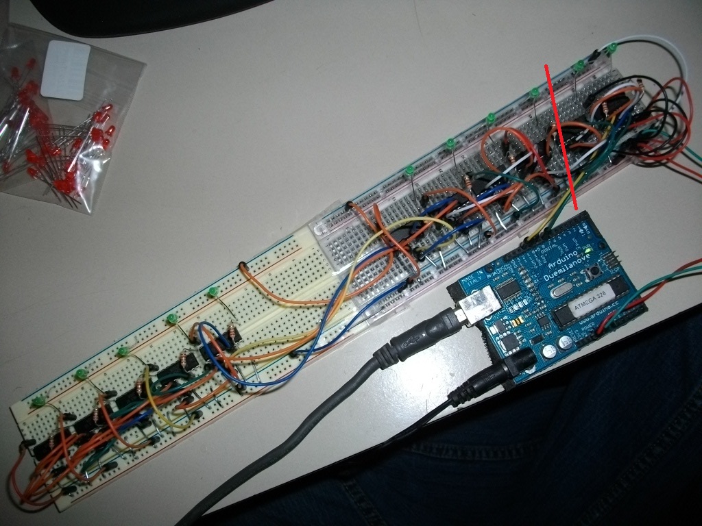
I can only get the Blink code example http://arduino.cc/en/Tutorial/ShftOut22 to work if I disconnect the Shift register clock pin jumper going from the 2nd chip to the 3rd chip as noted by the red line in the image below. When it is disconnected, the LEDs blink in an unrecognizable pattern all the way down the board. Is there some aspect of the original code that stops it from working at all when wired for more than 2 chips? Do you think this is a CODE problem or a WIRING problem? I've double checked the wiring and all seems fine.
Can you define "works" for me? You say it works if you disconnect the wire, but "the LEDs blink in an unrecognizable pattern all the way down the board". So it doesn't work? What happens with the wire connected, exactly?
I would start by adding some decoupling capacitors between the Vcc and Gnd pins of each chip.
[quote author=Nick Gammon link=topic=103839.msg778900#msg778900 date=1335843475]
I would start by adding some decoupling capacitors between the Vcc and Gnd pins of each chip.
[/quote]Why? What problem does that address and in what way?
You should be able to get any number of chips to work. I did some work on them here:
You need to chain them by connecting pin 9 of the first chip (Q7') to pin 14 (DS) of the second chip, and then pin 9 of the second chip to pin 14 of the third chip and so on.
I found the sketch a bit confusing, but with your 11 chips something like this should push a pattern onto all of them
 digitalWrite (LATCH, LOW);
  SPI.transfer (0xAB);  // chip 1
  SPI.transfer (0xCD);  // chip 2
  SPI.transfer (0xEF);  // chip 3
  SPI.transfer (0x42);  // chip 4
  SPI.transfer (0x55);  // chip 5
  SPI.transfer (0x66);  // chip 6
  SPI.transfer (0x77);  // chip 7
  SPI.transfer (0x88);  // chip 8
  SPI.transfer (0x44);  // chip 9
  SPI.transfer (0x22);  // chip 10
  SPI.transfer (0x3C);  // chip 11
  digitalWrite (LATCH, HIGH);
Basically you need one SPI.transfer per chip, and as each one goes in it gets pushed out to the next chip.
[quote author=Nick Gammon link=topic=103839.msg778899#msg778899 date=1335843371]
Can you define "works" for me? You say it works if you disconnect the wire, but "the LEDs blink in an unrecognizable pattern all the way down the board". So it doesn't work? What happens with the wire connected, exactly?
[/quote]Works means LEDs light up in some way, even if not as intended. Doesn't work means LEDs don't light up at all.
David82:
Why? What problem does that address and in what way?
Read Grumpy Mike's tutorial about them:
http://www.thebox.myzen.co.uk/Tutorial/De-coupling.html
Basically by the end of the chain the noise from all that digital transferring may be corrupting the signal.
David82:
Works means LEDs light up in some way, even if not as intended. Doesn't work means LEDs don't light up at all.
You can check your wiring by simply bypassing the first couple of chips. In other words, connect MOSI not to the first chip but the third one. See what happens then.
can you post more complete code?
I do have Q7 -> DS connections going down the whole array as you described but I also have:
Shift register clock pin of chip one -> Shift register clock pin of chip two going down the whole array AND
Storage register clock pin (latch pin) of chip one -> Storage register clock pin (latch pin) of chip two going down the whole array as per the image below. Is that the wrong way to wire them?

[quote author=Nick Gammon link=topic=103839.msg778909#msg778909 date=1335844444]
You can check your wiring by simply bypassing the first couple of chips. In other words, connect MOSI not to the first chip but the third one. See what happens then.
[/quote]Which pin is MOSI? And what about the other data/latch pin connections going from the arduino to the first chip? They can just be left there while only moving the MOSI jumper?
I'm hoping you made a mistake with your diagram because D13 is SCK (which you have not connected) and D12 is MISO which you have connected but should not have.
Which pin is MOSI?
My page lists all the pins.
can you post more complete code?
#include <SPI.h>

const byte LATCH = 10;

void setup ()
{
  SPI.begin ();
}  // end of setup

void loop ()
{
  digitalWrite (LATCH, LOW);
  SPI.transfer (0xAB);  // chip 1
  SPI.transfer (0xCD);  // chip 2
  SPI.transfer (0xEF);  // chip 3
  SPI.transfer (0x42);  // chip 4
  SPI.transfer (0x55);  // chip 5
  SPI.transfer (0x66);  // chip 6
  SPI.transfer (0x77);  // chip 7
  SPI.transfer (0x88);  // chip 8
  SPI.transfer (0x44);  // chip 9
  SPI.transfer (0x22);  // chip 10
  SPI.transfer (0x3C);  // chip 11
  digitalWrite (LATCH, HIGH);
  delay (20);
}  // end of loop
And what about the other data/latch pin connections going from the arduino to the first chip? They can just be left there while only moving the MOSI jumper?
Look at the circuit on my page. You parallel up SS and SCK. MOSI (D11 from the Arduino) goes into DS on the first chip. Then the output of that chip (Q7') goes to DS on the second chip. And so on.
I see.
I've got it wired as you described and am using the code you recommended but am getting nothing.
Arduino D13 goes to SH_CP 11
Arduino D11 goes to DS 14
Arduino D10 goes to ST_CP 12
What can I do to troubleshoot it?

For a start, since you only have one LED per chip, change the transfers to be all 0xFF:
  SPI.transfer (0xFF);  // chip 1
  SPI.transfer (0xFF);  // chip 2
... and so on ...
  SPI.transfer (0xFF);  // chip 11
That way the LED should definitely light up.
Try that and see if at least the first LED lights up.
nope, they don't. I don't have the capacitors and 20k resistor like you show in your diagram. Is that critical? If I unplug the 5V jumper from the arduino, they all light up.

If I unplug the 5V jumper from the arduino, they all light up. Also, if I go back to your original code, they all blink randomly except the LEDs on the first two chips.
If I use the a modified version of your code (pasted below), then each one lights up and stays on, one by one until it gets to the end. Then they just randomly blink in no discernible order. I need to be able to send COM commands (0-87) which would light up any of the LEDs depending on the number entered. Similar to the first example code in the ShiftOut tutorial.
void loop ()
{
  digitalWrite (LATCH, LOW);
  SPI.transfer (0xAB);  // chip 1
  digitalWrite (LATCH, HIGH);
  delay (300);
}  // end of loop
I'm just making up an example to prove my general method works. This code toggles them so you can see something happening:
#include <SPI.h>

const byte LATCH = 10;

void setup ()
{
  SPI.begin ();
}  // end of setup

void loop ()
{
static byte c = 0;

  digitalWrite (LATCH, LOW);
  SPI.transfer (0xAB ^ c);  // chip 1
  SPI.transfer (0xCD ^ c);  // chip 2
  SPI.transfer (0xEF ^ c);  // chip 3
  SPI.transfer (0x42 ^ c);  // chip 4
  SPI.transfer (0x55 ^ c);  // chip 5
  SPI.transfer (0x66 ^ c);  // chip 6
  SPI.transfer (0x77 ^ c);  // chip 7
  SPI.transfer (0x88 ^ c);  // chip 8
  SPI.transfer (0x44 ^ c);  // chip 9
  SPI.transfer (0x22 ^ c);  // chip 10
  SPI.transfer (0xFF ^ c);  // chip 11
  digitalWrite (LATCH, HIGH);
  delay (200);
  c ^= 0xFF;  // toggle
}  // end of loop
So far I'm up to the second chip and it works fine. Now for the 3rd.
Looks like Christmas lights alternating on and off except even more randomly. What was it supposed to look like? If I pick one, at random, and watch it, it blinks at one rate, turs off briefly, then on for a bit, then back to blinking. Seems to be no pattern to them all. Is there a way I can tell each specific one to turn on or off?
With my code they should blink very evenly. Here is how I wired it:

- Blue wire: SS (D10)
- Orange wire: SCK (D13)
- Green wire: MOSI (D11)
Note that the green wire only goes to pin 14 of the first chip. Then pin 9 of the first chip goes to pin 14 of the second chip (from the right). Then pin 9 of the second chip goes to pin 14 of the third chip, and so on.
With that code the LEDs should alternate exactly every 200 mS. No randomness.
Sketch:
#include <SPI.h>

const byte LATCH = 10;

void setup ()
{
  SPI.begin ();
}  // end of setup

void loop ()
{
static byte c = 0;

  digitalWrite (LATCH, LOW);
  SPI.transfer (0xAB ^ c);  // chip 1
  SPI.transfer (0xCD ^ c);  // chip 2
  SPI.transfer (0xEF ^ c);  // chip 3
  SPI.transfer (0x42 ^ c);  // chip 4
  SPI.transfer (0x55 ^ c);  // chip 5
  SPI.transfer (0x66 ^ c);  // chip 6
  SPI.transfer (0x77 ^ c);  // chip 7
  SPI.transfer (0x83 ^ c);  // chip 8
  SPI.transfer (0x44 ^ c);  // chip 9
  SPI.transfer (0x22 ^ c);  // chip 10
  SPI.transfer (0xFF ^ c);  // chip 11
  digitalWrite (LATCH, HIGH);
  delay (200);
  c ^= 0xFF;  // toggle
}  // end of loop