I am attempting to build a BASIC interpreter based off of a ATMega328. Essentially I will be taking the customised TinyBASIC library (Or similar) and a slimmed down version of the TVOut library (Also customised) and loading it onto a custom board with a PS/2 port and RCA jack. I have completed the schematic for this and would be really thankful if someone could look over the board design just to check it will work. Basically its a ATMega328 development board, with a RCA jack and PS/2 port.
When creating schematics, it always helpful to add the LETTER_L frame (or whatever paper size you want to use) from the Parts Library. I usually place the left bottom corner at 0,0.
When when you print, you can select the same paper size and a scale factor of "1". This will keep your PDF from being split across pages.
Yeah I am not sure about why the schematic is split over two pages. The diode is for short circuit protection. I will give you an overview of what I really want to accomplish here. Recently I watched the movie Jobs, and I thought it would be awesome to build something akin to the Apple I. With a basic text console, and running BASIC. I was thinking about adding a SD card, which means I should be able to follow most of the code in here Arduino BASIC Interpreter Using LCD, Keyboard, And SD | Hackaday, making it a bit easier, all I would really have to do is customize it and setup the TVOut library. If need be, I could always skip using the Arduino bootloader and flash directly to the chip, but that would be a LOT more work. So is my board design sound?
As it stands that diode will provide very brief protection against reverse voltage, and nothing else. I say "very brief" because if you apply a reverse voltage to the input the diode will almost instantly vaporise thus removing said protection. The rest of the circuit will follow in (roughly) two fifths of five eights of a poofteenth of a mS.
If you add a PTC you can get reverse protection. As for "short circuit" protection you may have to describe that better.
Now to the basic design, is it possible to get a decent interpreter into the 328? If so is there enough RAM to hold the user's source code? Is it possible to run an interpreter at the same time as generating raw video?
From that Hackaday article
this implementation of BASIC has you start each line of code with a line number, and doesn’t allow for character editing once the line has been input.
Frankly that is useless as it stands, maybe OK as the base for something better but if that's the end goal I'd stop now.
You may be interested in this design which I think does what you are intending.
Sorry about the pdf file being on two pages. Here is the revised one. Also I have found something that should clear up a few doubts, TinyBASIC on home-made microcomputer - YouTube, there is an example of someone who has got this working. And if I add a SD card, then I can make it load programs off of it, as this is a feature of TinyBASIC. So is anyone able to confirm if this board schematic is going to work?
Also, I followed the Make your own D*mn board tutorial for a lot of this, if the diode is removable, I will remove it. But if it does add any protection whatsoever, I may as well keep it.
But what can you actually DO with this, does it have IO ability etc. Anyway it will be a fun project.
The schematic looks ok, I can't comment on the header pinouts for SV1 and the keyboard as I'm not familiar with them. The reset signal from the ISP header normally goes directly to pin 1 (Reset) not to the other side of the auto-reset cap as you have it.
But if it does add any protection whatsoever, I may as well keep it.
It does nothing as far as I can tell. I see in that tute he says it will "prevent damage if power is accidentally connected backwards." I don't see that, wire that backwards and it will blow up unless the power supply limits the current. Maybe I missed something, but it won't do any harm.
Graynomad:
But what can you actually DO with this, does it have IO ability etc. Anyway it will be a fun project.
I do plan on having IO capability, that is what the big female header is for. Other than that fun things like a text game and Hello World. Also I will write a few routines that can make it easy to test equipment, before I create the actual board design I may add a couple of things like motor drivers, servo drivers etc.
Graynomad:
The reset signal from the ISP header normally goes directly to pin 1 (Reset) not to the other side of the auto-reset cap as you have it.
Thanks, I have fixed that.
Also, can anyone give me a quick explanation on which pins to connect for this here SD/MMC Socket - PRT-12769 - SparkFun Electronics, its the SD card socket I wish to connect, but I have never used a SD card before in an Arduino project. Also with the TVOut library, I believe it will be very easy to reduce the size of it significantly. I would love to be able to have colored text in this project, but it looks unlikely. Is there anyone who believes it may be possible to get colored text in here?
Is there anyone who believes it may be possible to get colored text in here?
I think Nick Gammon experimented with colour but found it was a bridge just a little to far.
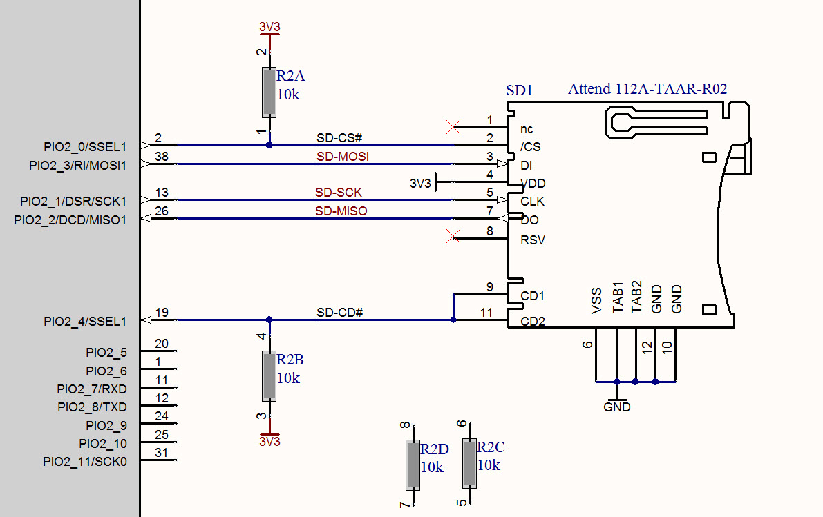
As for the SD interface, attached is a schem I used on a project, it may be some help but it's a different card holder so the pin #s will be different. Most pins are self-explanatory, there are 4 data pins but you only use 2 of them in SPI mode and off the top of my head I can't remember which 2, I assume D0 and D1 but maybe not.
If you're really serious about making a BASIC interpreter with stuff like motors, sensors, SD cards and such, maybe you should consider something other than the ATmega328.
Why not use the ATmega2560? You'll start out with 8K of RAM (2X the original Apple I) and it supports extending the RAM with an external chip. Maybe don't add the external RAM on the first board, but add it later on.
You'll have I/O for your on-board stuff with plenty left over for the user to do whatever they want. The overall design isn't much more complicated than the ATmega328, though the PCB layout is a little bit more important given the chip's package.
The motor driver and servo stuff was more of a idea, not really serious. I would prefer to make the board work for the 1st revision, then add the ATMega2560 in a 2nd revision.
CrossRoads:
SD cards need couple hundred mA of 3.3V VCC and 3.3V level signals. 74HC4050 commonly used for level conversion.