Hello guys "thanks in advance for all you guys do to help"
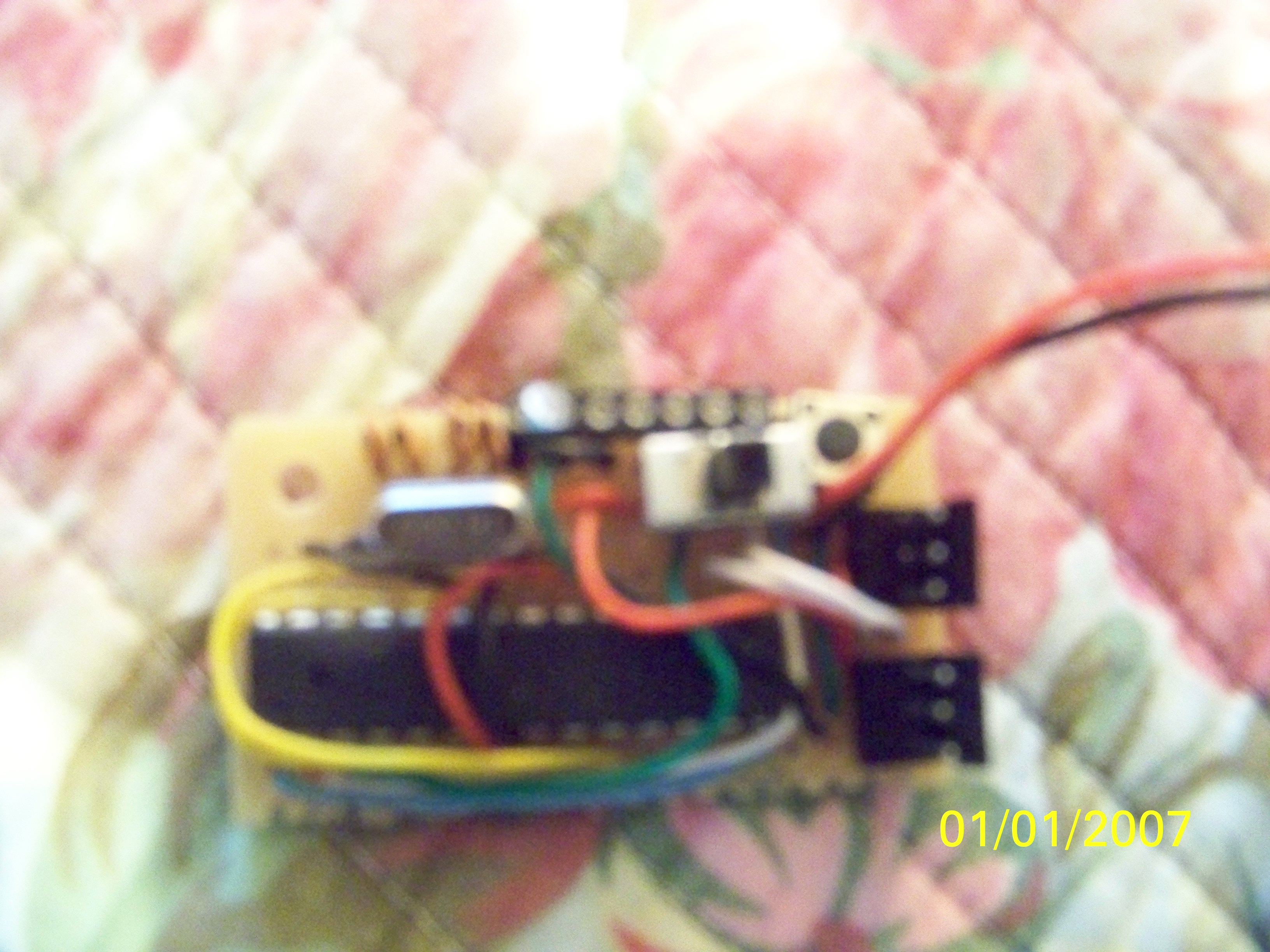
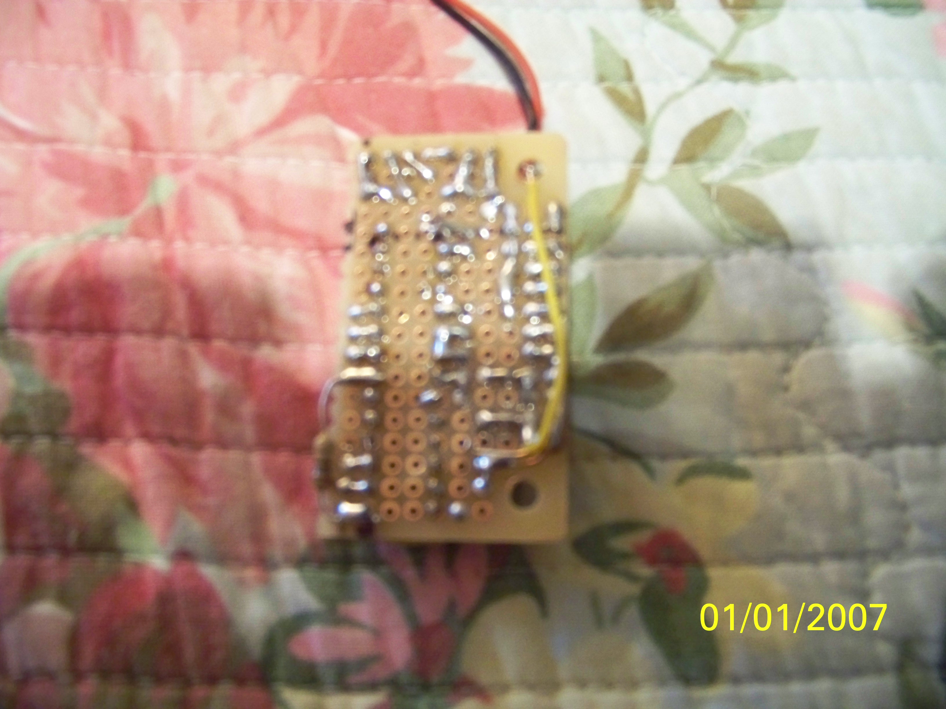
I have a project that I proved out on proto board and then moved it to a soldered board. "the servos were attached when proving it out"
Its a stand alone ATmega328p-pu chip "over kill" which only uses pins D9 , D10 as out puts to servos, Pin Ao is random generator "nothing wired to it".
The code is below and as I stated before it worked great on proto board with servo's. I transfer it to the soldered board and incorporated a reset button, power switch and UART port to check/change the program. Reset is tied to +5v via 10ohm resister. The program runs fine as long as the servo's are not plugged in "watching cases on serial monitor". Once I plug in the servos the program stops randomly on one of the cases and always stops after running case 11. If I hit the reset button it will resume again only to stop again later.
Not trying to answer my own question, but I assume I need to condition the servo surges some how.
Any suggestions on how to fix this issue would be much appreciated.
Thanks in advance.
// Moves servo's to given position based on random case number.
// case number is output to serial monitor.

#include <AFMotor.h>
#include <Servo.h>
long randNumber;
const int analogInPin = A0;  // Analog input pin

Servo servo1; //= pin D10
Servo servo2; //= pin D9
//----------------------------------------------------
void setup() {
  Serial.begin(9600);
  randomSeed(analogRead(0));
  servo1.attach(10);
  servo2.attach(9);
}
//-----------------------------------------------------

void loop() {


  randNumber = random(0, 12);  // print a random number from 0 to 11
  Serial.println(randNumber);
  delay(50);

  switch (randNumber){
  case 0:
  Serial.println ("case0");
  servo1.write(140);
  servo2.write(62);
  delay (4000);
break;

  case 1:
  Serial.println ("case1");
  servo1.write (85);
  servo2.write(135);
  delay(4000);
  break;

  case 2:
  Serial.println ("case2");
  servo1.write (90);
  servo2.write (140);
  delay(4000);
  break;

  case 3:
  Serial.println ("case3");
  servo1.write (95);
  servo2.write (145);
  delay (4000);
  break;

  case 4:
  Serial.println ("case4");
  servo1.write (70);
  servo2.write (92);
  delay(4000);
  break;

  case 5:
  Serial.println ("case5");
  servo1.write (110);
  servo2.write (140);
  delay (4000);
  break;

  case 6:
  Serial.println ("case6");
  servo1.write (70);
  servo2.write (130);
  delay (4000);
  break;

  case 7:
  Serial.println ("case7");
  servo1.write (70);
  servo2.write (130);
  delay (4000);
  break;

  case 8:
  Serial.println ("case8");
  servo1.write (70);
  servo2.write (130);
  delay (4000);
  break;

  case 9:
  Serial.println ("case9");
  servo1.write (70);
  servo2.write (130);
  delay (4000);
  break;

  case 10:
  Serial.println ("case10");
  servo1.write (70);
  servo2.write (130);
  delay (4000);
  break;

  case 11:
  Serial.println ("case11");
  servo1.write (130);
   delay (200);
  servo2.write (72);
  delay (200);
  servo1.write (70);
   delay (200);
  servo2.write (140);
  delay (200);
  servo1.write (130);
   delay (200);
  servo2.write (72);
  delay (200);
  servo1.write (70);
   delay (200);
  servo2.write (140);
  delay (200);
  servo1.write (130);
   delay (200);
  servo2.write (72);
  delay (200);
  servo1.write (70);
   delay (200);
  servo2.write (140);
  delay (3000);
  break;
    }
  }
I'm still a newbie, the straight answer is no. Besides the caps for the crystal, the crystal and the 10ohm resistor for reset, there is nothing else.
Could you tell me the why it's needed and how to calculate for it so I won't ask these newbie questions here again?
Start with 0.1uF and 1uF ceramic capacitors from VCC to ground, as close to the ATmega328p.
Decoupling caps help to "decouple" the chip from the power supply so that when there are fluctuations, the chip's supply voltage stays clean, preventing random issues.
This is Grumpy_Mike's tutorial on decoupling: De-coupling
How are the servos powered? If from the same 5V as the Arduino board then there's the problem. (And of course the lack of decoupling will always have meant flaky behaviour)
I know for someone much smarter than me that info makes perfect since, but if I get the point right, the Cap. reduces spike noises to the IC from other devices on the circuit. Although theres no perfect reduction of noise, there is a sweet spot with the right value Cap. and begining with a low value Cap. you work up till it works correctly.
Is that about right?
I did solder a .01 pf to the +5 and gnd leads going directly into the IC with minimal change. Since the circuit is soldered down I figure I need to un-solder the .01pf and try holding the Caps to the incoming IC leads till I find the right one.
I did notice after I soldered the .01pf Cap. on, with only one servo plugged in the circuit worked fine.
RodneyD:
there is a sweet spot with the right value Cap
Yes and some people devote their entire careers to figuring out to calculate those values. Generally values like 0.1uF and 1.0uF together covers a large range of the issues.
When powering motors and such, large values like 47uF and 100uF can be useful for motors when they draw sudden large current.
RodneyD:
I did solder a .01 pf to the +5 and gnd leads going directly into the IC with minimal change.
0.1uF and 1.0uF. Not 0.01pF. Your solder blob might have that 0.01pF.
:~ I will get right on that 1.0uf cap right after I re-build the board. LOL ummm I let some solder fall across the two power leads to the chip and didn't notice till I saw the dreaded smoke.
Currently building another with many more things in mind, including an IC socket
I will let you know how it turns out.
Thanks for your help so far.
When you've built a new circuit the first thing you do is check for shorts between the
power rails using a multimeter - never just power it up and hope! In fact spend 10 minutes
actively looking for shorts and faults with that meter and you save a lot of time overall.
Double checking every chip has power and ground connected to the right pins is also simple
and worthwhile.
I actually did check all the solder joints with magnifying glass and my meter prior to firing it up the first time.
I just got lazy when I made changes. I have a nice digital power supply right in front of me that was saying your using way to much current here and I didn't see it either. You are correct, checking that saves money, time and frustration for sure.
I have a question.
I just received some attiny85 chips yesterday and switched gears on this project to see if I could quickly program a tiny to do the same for this project instead of the much larger atmega chip. I know the tiny will work for this but I'm having trouble understanding where and how the core files fit into the Arduino 1.0.5 program files.
All that I have read show putting the files in the "sketch folder" under a "hardware folder" which I assume is where they put it in the older programs. I'm only familiar with Arduino 1.0.5 and it has obviously changed. The hardware file is under the main program Arduino 1.0.5 folder.
I tried dropping the folder for version (tiny -2-0100-0002) "core", "variant", "bootloader", and prospective.txt files in the hardware folder but they don't show up under tools/boards when you restart Arduino program. I would think these files need to be imbedded with in other Arduino files.
Are you familiar with attiny85 and do you know where to put these files in the newer Arduino 1.0.5??