Just a simple question that after hours and hours of googling i am no closer to the answer.
I have a Arduino based RGB controller hooked up to a single rgb led for prototyping(final product to have led strips around the room using mosfets). I have several "scenes" programmed to run when i select certain buttons on an ir harmony remote which ties into the arduino through a simple ir sensor.
My question now, i want to also have it as a simple ambilight system.
Is it possible to hook up the r, g, b and grnd connections from a VGA splitter out of my HTPC to analog inputs to the arduino and have the arduino map the values to power the RGB LEDs?
I have read a few places that i will need maybe some resistors and capacitors to help with interference? Or since the arduino is interpreting the signal i wont need this? Is the current coming from the video card too much for the inputs on the arduino?
This is beyond the capabilities of a standard Arduino. You would need a high-speed triple ADC to start. You'd need to analyze the HSYNC and VSYNC signals to identify regions around the edges of the display, then possibly integrate the values of those regions to retrieve a color average. It's not a trivial project.
So the amblone is a great option but i was looking for a way to avoid having the computer do all the processing. I have heard it can be quite consuming. My HTPC is a pretty good system but i uaing it as my security cam server with 5ea - 648 x 480 ip cameras streaming and recording nearly 24/7.
I wasnt really looking to just sense the edges, an overall r, g and b value would suffice. Is that just not possible?
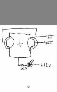
It looks like this should do what I want. The only difference would be that I would change the 12v in this schematic to the 5v, and the emitter on the RGB Lines would go directly into A0, A1, and A2 on the Arduino.
Would I need to change any of the values of the components(resistors, capacitors) because I am going to be using 5v instead of 12v? Would I need to arrange it differently?
So my brain has been racking, trying to find an easier way to do this, and remove the arduino from the equation when doing the ambilight function. I think I figured it out. Will this fry everything? Or will it be my savior?
I would have three of these circuits, one for R, G, and B. Control Pin 1 would be what I would use to set the led to a color or use one of the preset fade functions, and the second would be if I set the arduino to Ambilight mode and it would directly parse the information from the VGA port and apply it via the mosfets to the LEDS.
Would be interesting to see what effect you get here. You'll have feedback on the overall blended colour of the screen rather than bleeding the edge colours of the screen out past the edges. My first impression is this would give you an ambilight effect that isn't (unless the whole screen is a colour) representative of what's on display. But like I say, very happy to watch and learn from your progress.
Well even with my current setup, using AtmoWin and 1 RGB Channel from my Arduino Micro, its actually a pretty good, and cheap I might add, representation. I would record on my cel camera, but the camera colors are WAAAY off. I will definetely share progress, when progress has been made.
I have found the best effect when I view Electric Sheep animations on Youtube, it looks awesome. Also I have found that cartoons look best, but even race scenes and explosions are a massive improvement over no ambient lighting at all.
its an interesting project but who uses vga cables in 2013
it would be realllly interesting if like a camera captures the screen and the data gets processed, but then i guess an arduino might not have the power. Maybe withsome colour sensors or something like that.
I once saw a guy mention the possibility of using photocells, with red, green, and blue filters to evaluate the screen, and then apply the values to the RGB Strips. Initially I figured the "white bleed" for the lack of a better term on the tv would throw it off too much, if you look at most LCD tvs from even a 60 degree angle, they have a significant saturation loss, so I figured this possibility would be out due to the fact that no one wants photosensors inbetween them and their tv. Now, more and more I want to try it, how awesome would that be? No processing, analog data, easy peasy. Any input?
On the main topic, i forgot to pick up capacitors this morning, I am going to have a working prototype of the first diagram as soon as I get those damn 1uf Caps. Side note, any suggestions for good reading on Caps? Cant quite grasp the concept to figure what to do when I need to change a diagram voltage. Increase, decrease, how much, how much is too much?
If the LEDS color value isnt too "choppy" ill leave it that way and use the double transistor switch for each channel(second diagram), however if its terrible, I may run an averaging code through the arduino, to smooth it out a little bit. Thats why I need to understand the CAPS, I cant run 12v into the Analog Pins on the Arduino, right? How would I reduce that down to a level the arduino could handle? A resistor?
Thanks for all the help, happy to see the project is gaining interest.
Who doesnt love frying their arduino by applying 12v to the 5v rail.......damnit.......
On the good side!
I got the VGA Ambilight set up!
Pics:
Disclaimer: I use an All-In-One for my main computer at work, the laptop the VGA is connected to is ARCHAIC and for some reason wont let me mirror the desktop. The best I can do from work is display the background color on the LED, Screensavers are poo and youtube is soooo slow on this thing its terrible.
Well, need some more funds to replace the arduino..... But I will take this home tonight and see what it looks like running on a good system. I was thinking, maybe if its too choppy I could add capacitors in parallel with the wire running to each base, small ones, to create a slight fade, instead of an abrupt chop chop chop.
Hi there - thanks for sharing the info on this project!
I'm looking to do exactly the same thing and was wondering if you have a schematic of the finished working version. I'm also a newbie & don't recognise some of the components ont he board.
To answer some of the earlier questions about why I need this - I'm in a project called temp0rary ( temp0rary.com ) and we have a live VJ as part of the band. He's running his computer pretty hard with all the clips, so what we need to do is take the VGA signal from the projected visuals, do some very rough analysis of the R/G/B values, and then have LED lighting on stage that sort of follows what's going on with the visuals (i.e, if visuals are mostly red, the performers light up red too, dark is dark, bright is bright, nothing more than that really...)
Because we already have a lot of kit, and the laptops on stage are already dangerously close to maxed out, it makes more sense to split the VGA, analyse is in a quick & dirty fashion with an Arduino, and use that to squirt out RGB values to control the LEDs.
If anyone has any other info about controlling LED lights like these ones, please let me know!:
I followed MrWolf1701's schematic to a T, varying a few ohms here or there on resistors due to lack of exact matches on hand. I never ended up integrating it with the arduino, it actually works pretty damn well by itself. If you dont want to have other options, if you only want it to be controlled by the VGA signal, an arduino may not be required. If you have any specific questions about that schematic I am more than happy to help out. The project never got completed, I bought a 3d printer and cant get enough of it, nuff said. The uncompleted project(as you see it in the pictures above) is actually here in my office right behind me.


