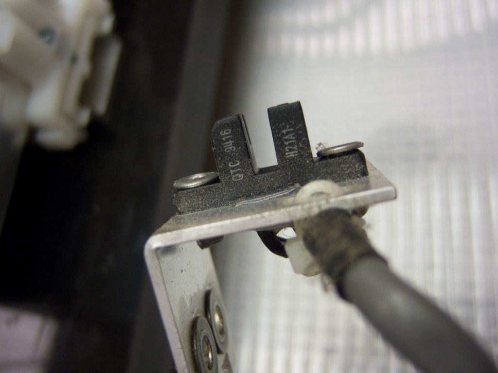
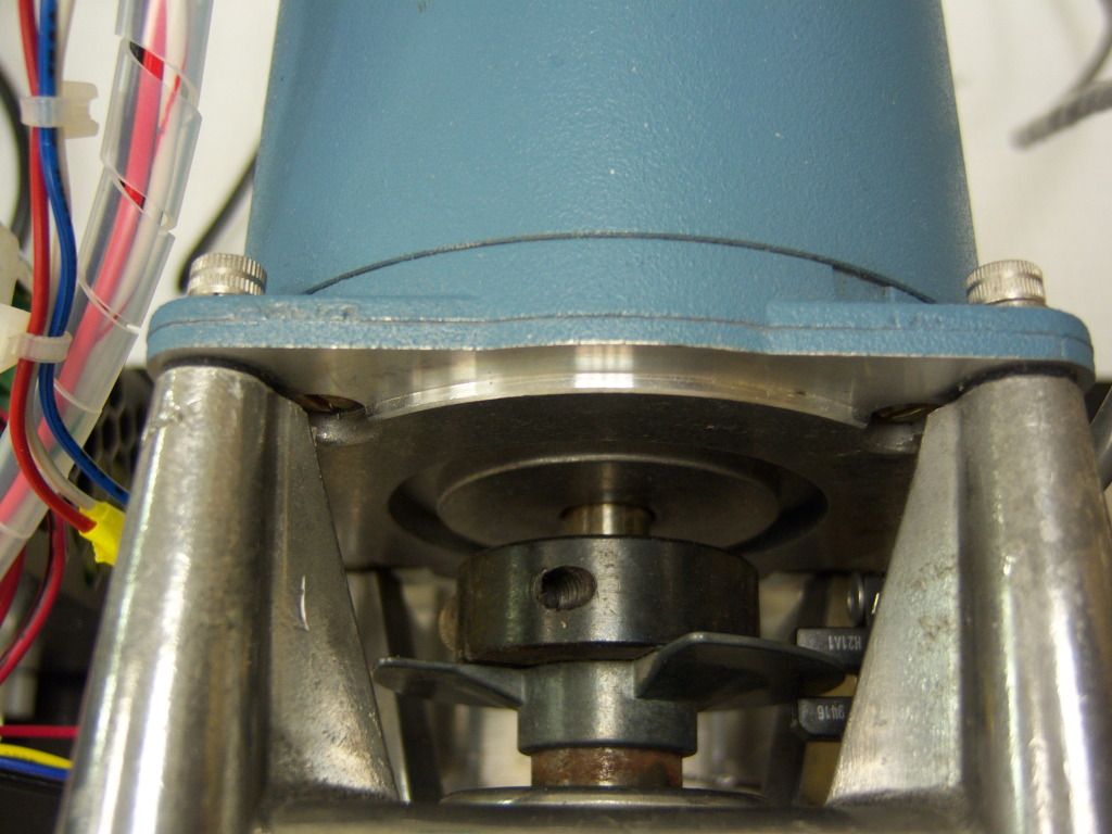
Can someone tell me how to use this sensor to measure rpm on a stepper motor. Specifically I would like to know how this sensor works and how to connect the 4 pins from the sensor to my arduino. I have attached the data sheet for a similar sensor (i think).
xan213:
Can someone tell me how to use this sensor to measure rpm on a stepper motor. Specifically I would like to know how this sensor works and how to connect the 4 pins from the sensor to my arduino.
I think that once you know how to connect and read the sensor, the rest will follow.
I have attached the data sheet for a similar sensor (i think).
Where?
The 4 pins probably comes in pairs. Two of them is for the emitter (arduino +5 -> resistor -> arduino ground).
One of the other two is the output from the sensor .. but you'll have to look up what else. It's not unusual that the sensor can take a higher voltage than the +5 arduino.
