hi & good day to you tack,
ive got good news for you !
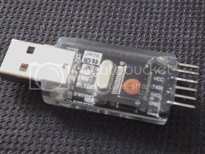
its definitely possible to get the PL2303 Module you have to get setup for Auto-Reset as i have made a whole bunch of them for a few buddies but ended up modifying about 40 of them in total lol !
Your right from looking in the PL2303 datasheet, Pin 2 on the SMD chip is the one responsible for the Auto-Reset signal and its not connected to anything on that board so you got two choices here:
either get hold of a CP2102 which has an easily solder-able DTR pin or try modding the PL2303 adapter you already have like mine !
Here's a bunch of photo's taken of my modified one, this one was the prototype and soldering it was pretty easu but tedious and took a while just getting it right but after the many DAYS/HOURS of finding a method that worked i can hopefully save you some trouble if your looking to do the mod yourself !
The trick is to always use flux, as Guru crossroads said, dont overdo it and here's my method that worked for me:
Tin the tip of your fav soldering tip a little, only enough to cover 2 (TWO) pins of the SMD PL2302 !!!
Yup you read that right, TWO Pins, lol !
What i found out by Days of trying NOT to get solder on two pins was that it is actually easier to take solder AWAY from & UNBRIDGE two SMD pins than it is to only solder one-pin !
So...
Ingredients:
1 x 1 Male Pin Header
1 x 0.1uF Capacitor (100nF)
Method
Get your 0.1uF Capacitor and trim the leads like so:
Pic 1
- Get a fine file and gently shave down the back-side of the capacitor so that it sits right on the PL2303 chip, trust me, this works well lol !
Pic 2
Now these next photo's are from my really basic and cheap USB Microscope so the quality is not great but if you view these photo's in a small window (save to desktop etc !) then you will be able to see them better !
Place the Capacitor in top of the PL2303 Chip with the short leg bent onto the top of Pin-2 and you might want to literally add a TINY amount of super-glue to the back shaved-down side of the capacitor so that it doesnt move when your soldering, but i mean the SMALLEST amount, just enough to 'Tack it down temporarily' !
Pic 3

Apply Flux to Pin-1, Pin-2 & the Short Capacitor Leg, Tin your iron's tip with just enough solder to cover both Pins 1, 2 & the capacitor leg:
Pic 4

Pic 5

Now here's the trick !
As i found out, its imperitively much easier to bit-by-bit REMOVE solder from these two BREDGED SMD Pins by 1st getting rid of all the solder from the iron's tip, dipping the tip into some flux, i use a grease-like flux, NOT rosin-based, and remove the tip from dipping it in the flux quickly so that a drop of flux stays on the tip, touch the tip onto Pins 1 & 2 of the PL2303 chip and little-by-little remove the excess solder until the solder is only covering Pin 2 and the capacitor leg !!!
Heres a few pics in succession:
Pic 6

Pic 7

Pic 8

Pic 9

And then solder the 1 Male Pin-Header to the other side of the Capacitor and bend it so that it lines up with all the other pins of the module and tack it down with some more superglue OR get a hot-melt glue-gun involved, its not pretty but it will work b-e-a-utifully always AutoUploading sketches !!
btw i used a mold i had made to encase the module in casting resin and then sanded & polished it !
here's a few more pics !
PL2303 Modded:
PL2303 Mass-Modding, lol:
PL2303 Mass-Modding, lol (2):
The Finished Articles:
if anything isnt clear or you want me to explain anything just let me know & i'll be happy to help out !
have fun !


