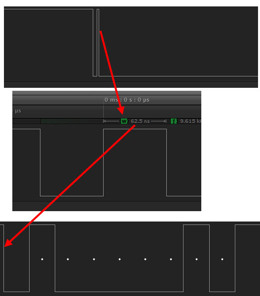
I am detecting 62.5ns glitches on some falling edges of async data coming out of an UNO pin 2 (for the attached code).
If you have a logic analyzer can you confirm this?
/*
  ASCII table

 Prints out byte values in all possible formats:
 * as raw binary values
 * as ASCII-encoded decimal, hex, octal, and binary values

 For more on ASCII, see http://www.asciitable.com and http://en.wikipedia.org/wiki/ASCII

 The circuit:  No external hardware needed.

 created 2006
 by Nicholas Zambetti
 modified 9 Apr 2012
 by Tom Igoe

 This example code is in the public domain.

 <http://www.zambetti.com>

 */
void setup() {
 //Initialize serial and wait for port to open:
  Serial.begin(9600);
  while (!Serial) {
    ; // wait for serial port to connect. Needed for Leonardo only
  }

  // prints title with ending line break
  Serial.println("ASCII Table ~ Character Map");
}

// first visible ASCIIcharacter '!' is number 33:
int thisByte = 33;
// you can also write ASCII characters in single quotes.
// for example. '!' is the same as 33, so you could also use this:
//int thisByte = '!';

void loop() {
  // prints value unaltered, i.e. the raw binary version of the
  // byte. The serial monitor interprets all bytes as
  // ASCII, so 33, the first number,  will show up as '!'
  Serial.write(thisByte);

  Serial.print(", dec: ");
  // prints value as string as an ASCII-encoded decimal (base 10).
  // Decimal is the  default format for Serial.print() and Serial.println(),
  // so no modifier is needed:
  Serial.print(thisByte);
  // But you can declare the modifier for decimal if you want to.
  //this also works if you uncomment it:

  // Serial.print(thisByte, DEC);


  Serial.print(", hex: ");
  // prints value as string in hexadecimal (base 16):
  Serial.print(thisByte, HEX);

  Serial.print(", oct: ");
  // prints value as string in octal (base 8);
  Serial.print(thisByte, OCT);

  Serial.print(", bin: ");
  // prints value as string in binary (base 2)
  // also prints ending line break:
  Serial.println(thisByte, BIN);

  // if printed last visible character '~' or 126, stop:
  if(thisByte == 126) {     // you could also use if (thisByte == '~') {
    // This loop loops forever and does nothing
    while(true) {
      continue;
    }
  }
  // go on to the next character
  thisByte++;
}
b) That has to be a measurement error. Maybe you're getting so much ringing in the wires that whatever it is you're using to look at the signal is seeing a pulse. Try shorter wires. Use a better measuring device. Use an analog scope to see the true signal instead of a squared-off version of it.
Its vital to keep logic analyser probe wires short and to run a ground wire parallel
and as close to the signals as possible, otherwise you've just created an inductor which
will ring (LC circuit with the probes input capacitance). Loops are inductors.
You get a lot less ringing with a 10:1 divider scope probe as the capacitance
is much less.
If you have a scope and switch to 1:1 you'll see longer slower ringing on edges
as the larger capacitance reduces the resonant frequency.
Occam's razor: If it was a real pulse I think other people would have noticed by now.
You could try putting the probe directly on the pin of the Mega328 (pin 3 is TXD) and see what you get. Make sure you get a really good ground as well, eg. touch the ground probe to the metal USB socket.
The difference in ringing if you do that can be massive - 60-70% less according to my new 'scope (as compared to connecting to two breadboard wires stuck in the Arduino's edge connector).
There's some bad news though: If that makes the pulse disappear then your logic analyzer is junk.
(don't those saleae things have an adjustment for what they class as low/high voltages?)
It may be that the probes are cheap without termination to prevent reflections...
Reflections from a probe cable can contribute to transient excursions. You need
to understand both RF engineering and transmission line theory to fully appreaciate
what happens in these circumstances.
The transmission line theory was developed back in Victorian times by Heaviside
who was working with much lower frequencies over much longer distances (electric
telegraph and the first undersea cables).
Fungus and Mark
Great full for your suggestions and comments.
Probes are simple wires connected to the instrument header.
I used heavier and shorter probe/ground wires (2 inches) plus went right to the pin as fungus suggested.
The glitches disappeared.
Thanks to you both!
polymorph:
The shortness is much more important than the gauge of the wires.
Actually the gauge has an effect, thin wires have more inductance than fat, but the
dependence is logarithmic so not very dramatic.
If you are driving a transmission line the best arrangement is to match the characteristic
impedance of the line, then the length of wires is irrelevant as the entire system becomes
resistive. However coax cables have lower characteristic impedance than a pair of wires
side-by-side (in most practical geometries) so this goal is not achievable and shortness
is key.
MarkT:
Actually the gauge has an effect, thin wires have more inductance than fat, but the
dependence is logarithmic so not very dramatic.
Inductance will be almost negligible at the sort of currents we're talking about here... (microamps)
That's at DC, with logic edges everything is different, we are in the realm of
transmission line and RF theory. The currents that flow during a logic transition
to charge up the line at not microamps, they can easily be 10's of mA, or into a
significant capacitive load even higher. Remember the transition edges can be
changing at 10^9 to 10^10 V/s
Going from 28 gauge to 12 gauge, 1cm of wire goes from 8nH to 4.7nH.
Compare that to the typical oscilloscope probe ground wire that is probably 24 gauge, about 4 inches (10cm) long, shortened to 0.5cm. 118nH versus 3nH.
Good scope probes will come with something that looks like a spring with a short straight part on it. That is meant to make a very short ground connection.
It goes over the ground on the tip like this:
Yes, the ground wire length is just as important as the probe tip. Even working on CRT TVs and VCRs, you'd run into weird ringing unrelated to the problem you were searching for that would turn out to be merely bad ground wire placement.
This has no more to do with a Saleae device's quality than would spurious ringing on a Tektronix scope due to poor choice of ground and probe tip wires.
Regarding the glitches (which appears to have been resolved), there's one thing that may have been overlooked. The glitches may not have actually been there ... that is the noise levels may be within the specified noise margins of the logic.
The logic analyzer will only show whats happening at its trigger LEVEL (voltage).
For instance, if its set anywhere from 0.1V to 2.6V, then your only viewing noise or ringing in the form of glitches that will no effect on the ATmega328 ... its logic remains at 0 for noise <= 2.6V with 5V power supply. In the datasheet, see Figure 35-5 ATmega328P: I/O Pin Input Threshold Voltage vs. VCC.
On my logic analyzer, I vary the the trigger level from min to max to see where glitches or artifacts appear at each limit, to get an idea of how clean the signal really is, if its within spec or if I need to grab a scope to get an analog visual.