JeanneD4RK:
It's not very important to be able to identify each sensor.
Well, I didn't see this until after I put in the work to give a comprehensive answer to this, so for others who might "tune in" later, here goes.
First, I agree with ChrisTenone: serial is probably more reliable.
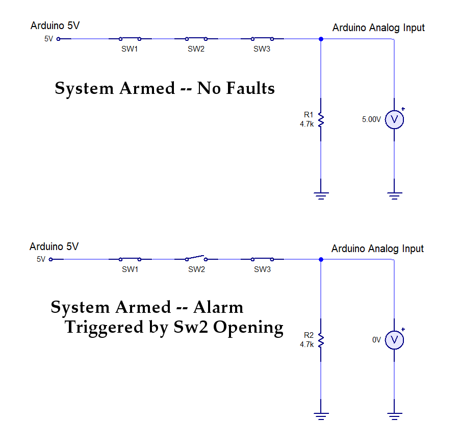
Here's the most basic system:
Just simple switches with no tamper detection. 5V at the Analog Input means, all is armed and well. 0V means a violation of the perimeter!
To defeat this, all a potential burglar has to do is short across one or more switches [i.e. *tamper with the switch*] and the premises can be entered from that protal [e.g. door, window, etc], without tripping the alarm. This could be done during "business hours" when the system is not armed, and when the "store" is open to the public.
To add tamper detection, resistors are added:
Notice how, with one of the Switch Assemblies shorted out, the voltage at the Analog Input is 2.58V, instead of 2.08V. When the Arduino script sees this, it can know that one of the switch assemblies was tampered with, and this can be presented to the User [i.e. the owner of the alarm system]. The typical algorithm would inform the User that the Alarm can't be set, because of tampering. The User would, then, walk the "perimeter" and try to find where the tampering occured, and remove it. Also, [not shown here], when one of the switches opens [perimeter violation], the voltage at the Analog Input goes to 0.
If this is a large facility, then the usual strategy is to divide the area into zones. If only one switch is used on each zone, then it's a simple matter to locate the tampering. But, if the Alarm Box has limited zones, and more zones are needed than the box can provide, then more than one switch can be used, in the manner shown, above -- in other words, what is shown in the schematics, above, is one zone, with three protected entities.
There is something called zone multiplication, which basically allows one zone to be multiplied into more than one zone. What that really means is, one set of terminals on the Alarm Box, can, by using this technique, be converted into more than one zone [if the box has this feature]. But, since we are the designers of the "box" we get to do this ourselves. And, here's how:
The different resistor values for R4, R5 & R6, result in different voltage levels, at the box, for different sub-Zone violations [a sub-Zone, in this case, are the zones that are created by zone multiplication [typically zone doubling, or zone tripling, etc.].
Notice how the voltage at the Analog Input is 4.13V when the system is armed, and there are no faults [i.e. all switches closed, and no tampering]. Watch what happens as the different sub-Zones are violated:
And, the voltage when one of the sub-Zones is tampered with:
By watching for these different voltages, you can interpret what is happening on the loop.
- 2.98V [or analogRead = 609] means sub-Zone 1 was violated [i.e. a door was opened, a window opened, or a window was broken, etc.]
- 2.61V [or analogRead = 534] means sub-Zone 2 was violated
- 2.26V [or analogRead = 462] means sub-Zone 3 was violated
- 4.38V [or analogRead = 896] means sub-Zone 2 was tampered with
- 4.13V [or analogRead = 844] means No Faults (everything's hunky-dory)
So, because we can tell which switch was opened [by a perimeter violation], this can be considered a zone because we know which switch it was [zones are all about being able to locate the activity].
And, in reality it is wise to allow for noise and resistor tolerance [probably best to use 1% resistors]. You can do this by watching a voltage range, making sure the range doesn't overlap one of the other voltage ranges. For instance, instead of just watching for 4.38V -- instead, watch for the range 4.28 to 4.4V [875 to 900].
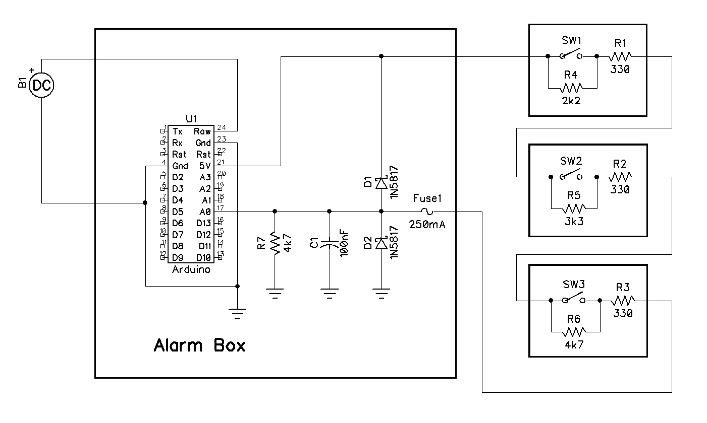
Here's a schematic showing a full system with input protection:
A note about the switch assemblies: I never understood the practice of having the the Reed Switch terminals exposed! This, it seems to me, defeats the purpose of the tamper sensing resistors. All the potential burglar needs to do is place a short across the switch terminals, and the whole tamper sensing system is defeated!! These resistors really need to be inside a box that can't be easily opened -- like a potted "brick". If I were to actually build this thing, I would use epoxy putty to encase the resistors--just putty them to the side of the reed switch that the terminals are on, covering those terminals in the process. Two wires would extend out of the epoxy, and those wires would, then, be wire-nutted to the feed line that connects it to the other switches, and/or to the Alarm Box.