Hey guys.
Perhaps i'm getting ahead of myself here, but i'd like to order some parts now so I can tackle the project over my christmas break.
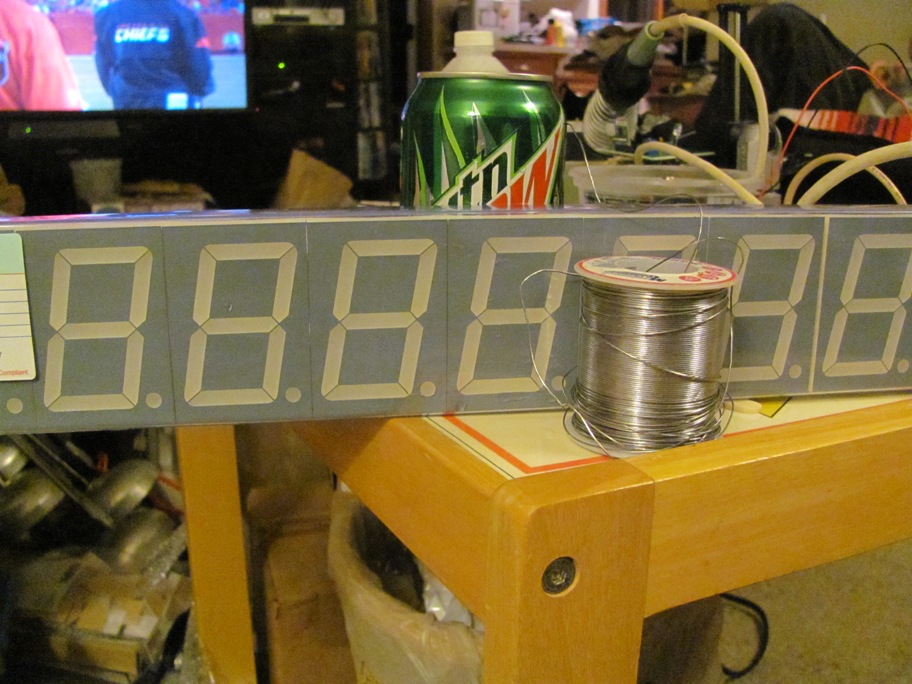
I'm planning to build an external display for PC racing simulators (ie. rFactor)
Ideally i'd like to have a display 12 digits wide, and 3 tall. [or taller depending on price/if the arduino can drive it]
I realize it would be a lot easier to use an LCD display, but i'd like to try and implement with segmented displays.
[Could I possibly use nine, 4-digit displays?, giving me a 12x3 display]
Similar to this (Arduino rFactor - YouTube), but with the LCD info on segmented displays.

My main concerns right now are:
- How to physically wire power to all of the displays. (using a 5v bench supply most likely)
- How to get the data from the arduino onto the displays. (multiplexing? hardware/pin wiring?)
- Fast display refresh rate.
Skip to part way through the video, and you can see how quickly his segmented display can respond to in-game changes.
I've seen similar setups on youtube, that have lag.
I've got a bootleg dealextreme Arduino Mega on the way, as well as an Arduino nano from the same site.
[I'm probably also going to need a pretty big breadboard, in order to have a somewhat continuous display. Or perhaps I should use something else instead of a solderless breadboard?]
If it ends up being prohibitively expensive, i'll probably go the LCD route, but i'd really like to do it on segmented displays.
EDIT:
I forgot to mention, I would like to have colon separators like on the (LTC-4627JR [These are available in Common Cathode and Common Anode]). It would make laptime displays much prettier.
EDIT2:
Or are these even available in the same size as that video? If not, i'll scrap the separator idea
Thanks for your help!
-Panici