High Power RGB LED Shield

After almost 4 months designing and prototyping, I finally got what I want to have.

High Power RGB LED Shield for Arduino

  • 700mA 3 channel LED driver based on lt3496
  • I2C controlled 3 channel PWM for dimming leds
  • dynamically adjustable current output ( can be used for analog dimming as well )
  • 42V input, 36V output. Drive up to 40W LEDs
  • 5V switching power supplier (up to 42V input)
  • many shield can be stacked and only use two I2C pins from arduino
  • optional temp sensor for monitor led temp and PCB temp

Check out the video, I will post detailed information, schematic, design soon.
You can find earlier design from my blog. http://neuroelec.com
If there are enough interest, I'm planning to sell it as well.

I am releasing schematic and board design of High Power RGB LED Shield under the Creative Commons Attribution-ShareAlike 3.0.
So, that should make the shield open source hardware :wink:

You can find eagle cad files, png, pdf of schematic and board design from google code.

http://code.google.com/p/neuroelec/source/browse/trunk/#trunk%2FHP_RGB_LED_Shield

Also, a software part of the shield is also released.
http://arduino.cc/forum/index.php/topic,51842.0.html

Not only just release the schematics and board design, But also I want to share my experience during the development of the shield.
Someone who want to design Arduino shield, LED driver, or modify the shield may find it helpful.
It will be three parts. If you find any in-accuracy or have suggestions on design, please let know.

Here is the first part: original writing is in my blog http://neuroelec.com/2011/02/designing-rgb-led-shield-1-led-driver/

Designing RGB LED Shield – 1. LED Driver

I will start to write why I chose particular chips and components while I designed the shield. It will be a expanded version of my first post. First part of the writing is about LED driver which is the part that I spent majority of time during development.

A primary reason for designing the shield was that I want to control high power RGB LEDs with the Arduino. There are many chips specifically designed as LED driver from many different companies. I need three independent channels to mix red, green, blue light to get any color I want.

A most common type of high power LED is 350mA one. These day, maximum current of high power LED is going higher and higher. Still common and easy to source types are 350mA and 700mA. So I looked at the LED driver chips that can power up to 700mA LEDs. Then, I found LT3496 from Linear Tech.

LT3496 is a just perfect chip for my designing goal. It has 45V, 1A internal switch that can drive up to 750mA. Best of all is three independent channels in a single chip which minimize the circuit and foot print. Since it can take up to 45V, it can drive 10 LEDs per channel, total 30 LEDs from a single chip.

Now, let’s take a look at what is LED driver is. LEDs need to be operated at constant current, otherwise they burn out quickly. LED driver is essentially a constant current power supply which can be linear mode or switching mode. Switching mode LED driver is a bit difficult to design, but it is way more flexible and efficient especially when it is going to drive different number of LEDs. So most of LED drivers are constant current switching power supply. Main differences between regular voltage regulated switching power supply and LED driver are current control and dimming circuit for LED brightness control. Dimming LED can be achieved by varying current limit or PWM input. Depending on how a driver circuit is designed, both of dimming methods can be implemented. Since I want to have RGB color mixing, dimming LED is a essential feature to have. I will write more about how I implement both dimming methods in a separate post.

In here, I will focusing on current mode switching power design. Constant current mode is achieved by regulating output current instead of voltage. Current monitoring is done by measuring voltage drop across a small value resistor (called current sensing resistor). There is a voltage drop across the resistor depending how much current flow. It is Ohm’s law. For example, when 1A current flow across a 0.1 ohm resistor, the voltage drop across the resistor is 1A x 0.1 ohm = 0.1V, 100mV (V = I x R). The driver monitor the voltage drop and make it constant. Rest of the part is regular switching power supply.

Basic components for switching power are switch, inductor, diode and input/output capacitors. One important factor of the design is switching frequency, how fast switch will turn on and off. Switching frequency is normally hundreds KHz to a few MHz. With high frequency switching, low value of inductor and capacitors can be used. So overall foot print of circuit is small and components are cheaper. But high frequency operation is not as efficient as lower frequency operation. Also switch itself dissipate more heat at higher frequency switching. Even though switching power is quite efficient, at high power output, switch will dissipate a lot of heat. Compromise between size/cost and efficiency/heat has to be made.

LT3496 operates from 330KHz to 2.1MHz. Linear tech’s reference design for the LT3496 runs normally at 2.1MHz. So the design is small and has low cost components. If input voltage and output voltage (number of LEDs) is fixed, you can still achieve relatively high efficiency. However if you don’t know or input and output voltage varies, it is very difficult make a circuit efficient at high operation frequency. Since I don’t know how many LEDs and what input voltage people will use with the shield, I can not optimize the circuit for a particular configuration.

To have flexibility of operation frequency, it is require to have high value inductor, which means bigger size, higher cost. The higher the inductance of the inductor, lower the ripple current to LEDs, lower minimum operation frequency. Among the same value inductors, bigger size inductor normally have higher current rate and lower DCR (resistance). Low DCR is important since it affects efficiency and amount of heat dissipation from the inductor. At high frequency operation, 10-15uH is normally good enough. For the large range of input and output voltages, I chose high value inductor, 47uH rated 1.5A. Rated amp looks overkill, but for 700mA operation at least 1A inductor is required and high amp rated inductor have low DCR. With the 47uH inductor, operation frequency can be as low as 330KHz depending on input and output voltage. Because of low ripple, output capacitor can be small which also helps for higher dimming ratio as well.

LT3496 can be configure for buck, boost, buck/boost design. In buck design, input voltage has to be higher than output voltage. However, it is most efficient and simple as well as allows high current output.

the final design of the LED driver handles LEDs pretty well. It has good current regulation, wide operation frequency, modest heat dissipation, low current ripples.

Later, I will post a page that summarize the appropriate operation frequency and input voltage depending on output voltage (number of LEDs) and a spread sheet that calculate recommended frequency and input voltage ranges.

Designing RGB LED Shield – 2. Dimming LEDs

Dimming LEDs is an important feature in powering LEDs. It is especially critical when you want to mix red, green, and blue to get color you want. As I posted before, there are two dimming methods, analog dimming and PWM dimming. Advantages and disadvantages of each were described before as well. http://neuroelec.com/2011/02/led-dimming-methods/

In here, let me tell you how I implement two dimming methods in the shield.

PWM dimming

PWM dimming is achieved by fast turn on and off. Depending on how long you turn on, brightness of LED is determined. Since the pulse of PWM signal is short, human normally don’t notice the turn on and off at higher than 100Hz. Dimming ratio is determined by turn on and off speed of LED driver. If LED driver can turn on and off LEDs within 1us, 1:3000 dimming ratio can be achieved at 100-150Hz PWM signal as long as PWM signal has a such precision.

Implementation of PWM can be simple, since Arduino can generate PWM. All I need to do is connect PWM output pins from Arduino to LT3496 PWM input pins. There is two problems with that. First one is Arduino PWM has two different frequency depending on pins(500Hz and 1KHz). Default frequency is a bit high and PWM signal is 8 bit resolution. So, dimming ratio you can get is 1:256. Second, more important one is there are only 6 hardware PWM pins in an Arduino which limit the number of shield can be stacked.

I really want to have shields to be stacked more than two. So I decide to put serial controlled PWM signal generator, ATTINY85, small and cheap AVR microcontroller. Attiny is is quite popular for this kind of things. As you may know there is a quite popular product, BlinkM is based on Atttiny. The idea is generating PWM signal from Attiny which communicate with Arduino by I2C protocol. The beauty of I2C is many devices can be controlled in a single bus which use 2 pins (A4, A5) in Arduino. So It does not matter how many shields are stacked, with just two pins we can control as many shield we want. I2C bus use 7 bit address so theoretically 128 shield can be stacked. In practice, maybe 20 stacked shields are maximum due to the rated current of stackable pins. If you independently power the shields, 100 may be OK.

Analog dimming

Analog dimming is not a popular method for dimming LED. Because of disadvantages that I describe before as well as requirement of adjustable voltage input. Many LED driver offer pins that limit the current flow to LED. Maximum current is set by current sense resistor, and driver can lower the limit by current adjust pin which normally take certain voltage. In LT3496, There are CTRL pins to limit the current. If the voltage to the pin is > 1V, the driver output maximum current set by current sense resistor. If voltage to the pin is < 1, the driver linearly decrease the output current. For fixed current limit, it is normally just tied to the internal voltage reference pin. Some led driver board left a spot for additional current sense resistor to lower the current limit or simple jumpers. More flexible driver boards have a trimmer or potentiometer to adjust current limit.

Ultimate flexibility on current limit can be achieved by either digital potentiometer or DAC. By using one of those not only you have freedom on current limit adjustment but also you have possibility of analog dimming. Since DigitalPot and DAC adjust output fast, it can be used for dynamic current adjustment.

As you see in my first post, I initially use digital potentiometer, AD5254 along with a resistor. It is basically variable voltage dividers. AD5254 is four channel pot and has eeprom to save the settings. Main problems of this approach are output voltage is vulnerable to input voltage change and accuracy of the resistors. Input voltage can varies in some extent. Also total resistance of the potentiometer is not accurate and different on each channels. To correct this problem, I need to put more components and make the circuit complicated. So I dropped the digital potentiometer. Instead looking into a DAC. There were three reasons why I chose AD5254. It is 8 bit potentiometer which is quite high resolution for potentiometer. It use I2C protocol, so I don’t need to waste any more Arduino pins. People who don’t need analog dimming, they can set current value into EEPROM, and forget about it. AD5254 read the values from EEPROM when powering up. Finding a DAC that has all those good things was not easy. Particularly DAC with the EEPROM is rare. Luckily, I found a perfect DAC for this. Microchip MCP4728 is I2C quad 12 bit DAC with EERPOM. Everything that I have in AD5254 with higher resolution and faster output. Even Availability and price was better. What can I ask more?

Three out of four pins are connected to CTRL pins of LT3496, one is connected to frequency adjustment pin. Now, Arduino control current limit of three channel independently and operating frequency. EEPROM of MCP4728 can store settings. Also, MCP4728 adjust current output within 1ms which is more than enough for analog dimming. Since 1ms adjustment time result in 1000Hz, you can even make analog dimming to pseudo-PWM.

MCP4728 has a programmable address feature. Users can set I2C slave address into EEPROM without physical jumper changes. Detailed explanation was posted before: http://neuroelec.com/2011/02/soft-i2c-and-programmable-i2c-address/

If you use analog dimming, maximum stackable shields are 8, since MCP4728 allow 8 programmable addresses.

Designing RGB LED Shield – 3. Power and Temp sensor

Independent power for the shield

Maximum input voltage of the Arduino is 20V. Recommended maximum voltage is 12V. Since the shield is buck LED driver, you can drive only 3 LEDs per channel with 12V. Otherwise, you need to supply two different voltage inputs: one for Arduino and ICs on the shield, the other for LEDs. Because of nature of linear voltage regulator, you can not use high input voltage for 5V ouput. The shield consume about 100mA of 5V for powering LT3496, Attiny85, MCP4728, and optional temperature sensor. 100mA is not that much, but none of small linear voltage regulator like 7805 can output 5V from 40V at 100mA. Because there is a 35V difference between input and output voltage, voltage regulator will dissipate 3.5W of heat at 100mA.

To have just one power for both Arduino and the shield, only choice left was another switching voltage regulator which have high voltage input. I found National LM2841 is good enough and simple to use. LM2841 is 42V input, 300mA switching IC. It is a bit more expensive that I hoped. Cheaper yet old type of switching ICs require larger foot print which I don’t have.

With the LM2841, 100mA is used for powering the shield. Rest 200mA can be used to power up Arduino. It also allow the shield is operated independently from Arduino.

Temperature sensor for LED and the shield

This is the one that I didn’t put it in my initial design and is totally optional. Some people want to monitor LED temperature, since temperature of LED is the most important factor that affect life time, color, current, voltage drop and so on. Maintaining LED temperature within acceptable range is mostly done by current limit and heat sink. When you can not have big enough heat sink or operates LEDs at high ambient temperature, you can maintain temperature by dynamically lower the current to LEDs.

Monitoring LED temperature can be done by putting temperature sensor close to the led. If the sensor is cheap enough, you can just glue the sensor close to the LED using thermal epoxy wherever you want. However temperature sensors are not cheap. Cheapest one is still cost about $1. You can not glue it every LED panel you have. The real cheap temperature sensor turn out to be transistors. It is cheap enough you can just glue them anywhere you want, and monitor the temperature when you need by connecting to Arduino. The most commonly used transistor for temperature sensor is 2N3906 which is a basic and common transistor. You can find them anywhere and is very cheap. You can buy 100 of 2N3906 at $4.

A bad side of using transistor as a temperature sensor is that you can not connect it directly to Arduino. It requires circuit for it. Luckily companies make lots of temperature sensor that utilize 2N3906 as a remote sensor. You don’t need any complex circuit. So I decide to put Texas instrument TMP421 on the shield.

TI TMP421 is a I2C temperature sensor. Once again I don’t use more than 2 pins from Arduino, those two I2C pins are still available for any I2C devices. TMP421 has an internal temperature sensor and one remote sensor input. On the shield, TMP421 is located close to LT3496, so I can estimate the IC temperature. Remote sensor input is pinned out right next to the LED connector, so you can connect to 2N3906 on LED board.

I got a couple of request for purchasing the shield. I decided to run first production (20 shields).

You can buy a fully assembled and tested shield for $37 from http://neuroelec.com/

There seems confusion about PWM frequency for high power LED dimming. I saw posts in forums about LED flickering especially at low PWM %. Some think they are seeing this problem due to low PWM frequency when they are driving high power LEDs. I want to point out that is highly unlikely the case. Here is why.

The PWM is a great way of dimming LEDs by adjusting ratio of on/off quickly. How quickly? The rule of thumb is higher than 100Hz frequency PWM make human can not see the flickering. When you see a movie, you are seeing 24Hz flickering. People barely tell it is flickering. When light is completely turn on/off, you need higher frequency than that. That’s about 100Hz. You can find more information about that by searching “flicker fusion threshold”

There are some cases where you want to have higher frequency PWM than 100Hz for LED. When you or your lighting source is moving, you may notice flickering at 100Hz due to the movements. Some very high current output LED driver or weird board design make you to hear PWM noise due to capacitor or something else ringing. Some people hear noises when they are driving motors with audible PWM frequency. That is a very rare case for PWM LED dimming.

Those two may be the only reasons why you need to use high PWM frequency for LED. Here are why you should avoid high PWM frequency for LED dimming for high power LED driver. When switching LED driver handle PWM signal, it is essentially turn on/off switching supply based on PWM signal. However it can not turn on/off at very high speed. Regular LED driver takes about 10-50us for on/off. Now let’s do a simple calculation. If PWM frequency is 100 Hz, each full PWM pulse is 10ms (1sec / 100). For 8 bit PWM dimming, each pulse need to divide into 256. So 1/255 pulse will be 40us. Now you are start to see a potential problem. Since some LED driver takes 50us to turn on/off, 40us pulse of PWM is not enough time. Now what you are start to see is half way on/off which result in flickering LED. Because most good LED drivers have on/off time close to 10-15us, you don’t see this kind of problem with 8 bit PWM with 100Hz frequency.

The problem is that Arduino has a two different default PWM frequencies (500Hz and 1000Hz) depending on pins. Now you see why some people saw these flicking like effect at low PWM duty cycle. If LED driver is connected to 1KHz PWM pin, LED driver need to turn on/off LED within 4us which is too short time even for the good LED driver. You may see flicking LED at low % PWM. To make this on/off time faster, some LED driver designs include additional transistors or mosfets which make LED driver to on/off less than 1us. My high power RGB LED driver shield also has mosfets even though it is not quite necessary.

There are PCB mount LED driver module like popular Luxdrive BuckPucks or some switching LED drivers from China. These may not be good even for 8 bit PWM dimming. For example, the BuckPuck has total 30us on/off time (15us each). They are recommending 50us. I know these are maximum values. Still they are barely OK for 8 bit PWM at 100Hz. If you use Arduino default frequency, they are definitely start to flickering at low PWM duty cycle (below 13/255 at 1KHz). You want to use low PWM frequency with those drivers not default frequency. It is not Luxdrive’s fault at all. Majority of LED drivers and modules are actually designed that way. Assuming that their drivers have flicker-less operation and 8 bit PWM dimming at 100-200Hz.

So you don’t want to use regular high power LED drivers with high PWM frequency and higher than 8 bit resolution PWM unless you know what you are doing. Naturally, analog dimming has no flickering problem, since you are not on/off LEDs.

This is incredible. I have yet to read all of your post, but this is really special. :slight_smile:

Thanks for kind words. I hope you enjoy reading. :slight_smile:

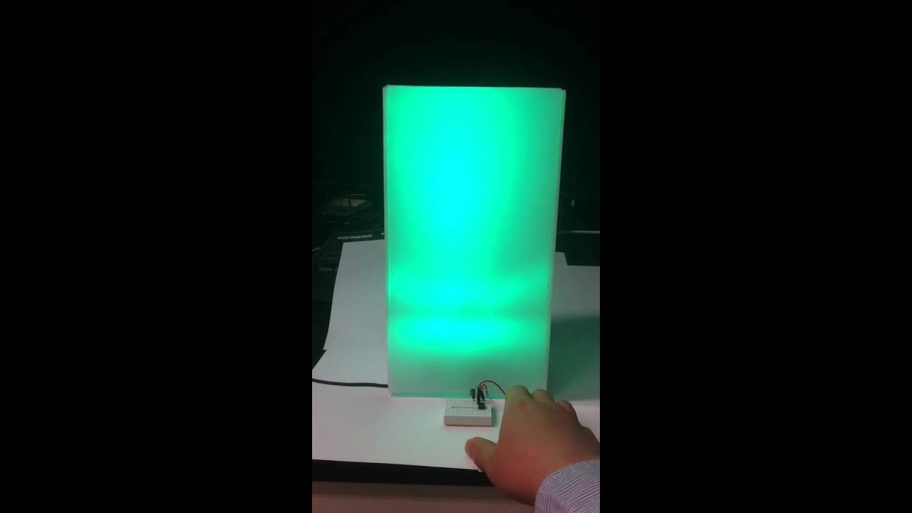
Here is a first demo project, RGB mood lamp.
Please find details from http://neuroelec.com/2011/03/color-changing-mood-light/

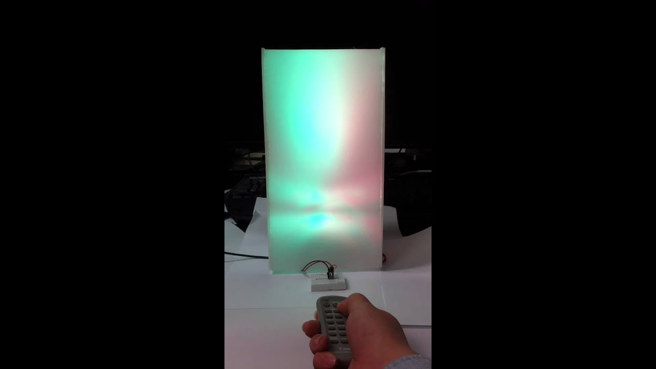
Another demo project, IR remote controlled RGB mood lamp.
Please find details from http://neuroelec.com/2011/03/ir-controlled-mood-lamp/

i love this shield

Two more videos of the shield demo projects. These are more of basic sensor tutorials.

RGB LED Mood Light Clock

http://neuroelec.com/2011/03/rgb-led-mood-lamp-clock/

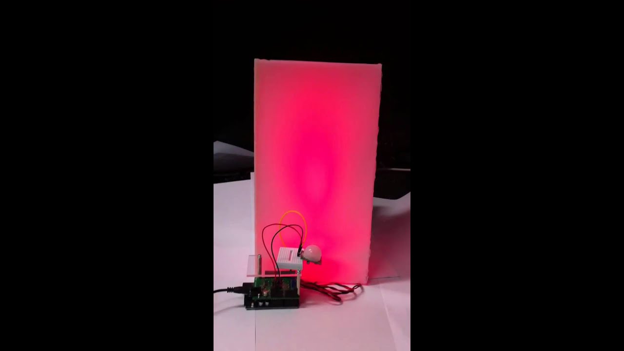
Intrusion Detect Mood Lamp

http://neuroelec.com/2011/03/intrusion-detect-mood-lamp/

LED Brightness to youreye, Gamma correction – No!

Original post with patched cyzRGB firmware : http://neuroelec.com/2011/04/led-brightness-to-your-eye-gamma-correction-no/

Human perceive brightness change non-linearly

When you want to change the brightness of LED or any light source, one thing you need to consider is how human perceive the brightness. As you see in the following chart, human perceive the brightness change non-linearly. We have better sensitivity at low luminance than high luminance. For example, when we control LED brightness using Arduino PWM, we see big brightness change between analogWrite(9,1) and analogWrite(9,2). We don’t see brightness change between analogWrite(9,244) and analogWrite(9,255). If you didn’t know, just quickly test yourself with Arduino. If you want to control LED brightness linearly to your eye, it require to have some adjustment.

Mis-understanding of Gamma Correction

In Arduino or any microcontroller, a common way to achieve linear brightness change is a lookup table that compensate or correct the value according to the curve. There are a common misunderstand or confusion regarding what curve to use. Many people use so called gamma correction table or equation which is not related with human perception of brightness. The Maxim App note http://www.maxim-ic.com/app-notes/index.mvp/id/3667 describe “Gamma correction is used to correct for the nonlinear relationship between luminance and brightness” which is simply wrong. The gamma correction is used to correct nonlinear relationship between applied voltage to CRT and luminance of CRT. Gamma correction - Wikipedia It is nothing to do with human perception. It is not just Maxim, I could find many implementation of gamma correction to correct luminance and brightness.

Why people so easily confuse about it? The gamma correction is necessary for the display application. When movie or image is displayed on LED matrix like a stadium display, you want to have gamma correction since movie and image data itself is already gamma corrected data. It is also useful for LED based LCD backlight. When LED is used for lighting, however gamma correction is irrelevant. A funny thing is co-incidentally gamma correction and human perception of luminance is very similar. http://www.poynton.com/PDFs/SMPTE93_Gamma.pdf Take a look at following chart. Again it is just a co-incidence. So somehow the gamma correction is close approximation of human perception the luminance.

Correction calculation of luminance and brightness describe in CIE 1931 report then used for CIELAB color space.

L* = 116(Y/Yn)^1/3 – 16 , Y/Yn > 0.008856
L* = 903.3(Y/Yn), Y/Yn <= 0.008856

Where L* is lightness, Y/Yn is Luminance ratio.

For the correction curve, you need to inverse the equation.

You can test linearity of LED brightness to your eye using following Arduino example code.

Just put any LED on pin 9 with current limiting resistor.

/*
 Change brightness of LED linearly to Human eye
 32 step brightness using 8 bit PWM of Arduino
 brightness step 24 should be twice bright than step 12 to your eye.
*/

#include <avr/pgmspace.h>
#define CIELPWM(a) (pgm_read_word_near(CIEL8 + a)) // CIE Lightness loopup table function

/*
5 bit CIE Lightness to 8 bit PWM conversion
L* = 116(Y/Yn)^1/3 - 16 , Y/Yn > 0.008856
L* = 903.3(Y/Yn), Y/Yn <= 0.008856
*/

prog_uint8_t CIEL8[] PROGMEM = {  
	0,	1,	2,	3,	4,	5,	7,	9,	12,
	15,	18,	22,	27,	32,	38,	44,	51,	58,
	67,	76,	86,	96,	108,	120,	134,	148,	163,
	180,	197,	216,	235,	256
};

int brightness = 0;    // initial brightness of LED
int fadeAmount = 1; 

void setup()  { 
  // declare pin 9 to be an output:
  pinMode(9, OUTPUT);
} 

void loop()  { 
  // set the brightness of pin 9:, 0-31, 5 bit steps of brightness
  analogWrite(9, CIELPWM(brightness));    

  // change the brightness for next time through the loop:
  brightness = brightness + fadeAmount;

  // reverse the direction of the fading at the ends of the fade: 
  if (brightness == 0 || brightness == 31) {
    fadeAmount = -fadeAmount ; 
  }     
  // wait for 500 milliseconds to see the bightness change    
  delay(500);                            
}

High Power RGB LED Shield 2.0

Here is a second revision of the shield. High Power RGB LED Shield version 2.0 has some improvements. A major change from version 1 is a new I2C PWM converter. The version 1 shield use ATTINY85 with cyzRGB firmware as a I2C PWM converter. Additionally it has couple of smart features like the writable sequence. However smart features was not that useful and it even confused users. I decide to abandon ATTINY with a better alternative, NXP PCA9685, a dedicated hardware I2C PWM converter. PCA9685 provide more muscle than brain. Instead of a few extra commands which was not popular, the shield now have more powerful PWM capability. All demo project codes that are posted are compatible with version 2 shield. It require Arduino or any microcontroller with I2C support for operation.

Overall design of the shield has not been changed except PCA9685. Price of the shield goes up little for the better quality product.

More Muscle than brain

NXP PCA9685 for I2C PWM

The PCA9685 support high speed I2C communication up to 1MHz (Now, all chips including mcp4728, tmp421 support high speed I2C). Arduino can support 400KHz I2C communication (default is 100KHz). Total 62 I2C address is supported, so 62 shields can be stacked or controlled from a Arduino.

12bit PWM resolution

12bit hardware PWM (4096 steps) is supported. 1: 4000 dimming ratio is achieved just with PWM. 12bit PWM allow smooth correction of brightness curve to human eyes at 8 bit.

Adjustable PWM frequency – 40-1000KHz

PWM frequency can be adjustable with default 200Hz. Version 1 shield use fixed 120Hz PWM. While >100Hz PWM is good enough most applications, in some cases you may find high frequency PWM useful. http://neuroelec.com/2011/03/high-pwm-frequency-for-led-good-or-bad/

Better Quality PCB

Smooth and clean edge by tab routing all around
Blue silk screen, gold finish
2oz (70um) copper for better heat dissipation
Official OSHW (open source hardware) logo , Maybe first Arduino shield with OSHW logo

Schematics and design files

As I do support open source hardware, all schematics and design files are available. If you need any eagle library for the parts, just let me know.

http://code.google.com/p/neuroelec/source/browse/#svn%2Ftrunk%2FHP_RGB_LED_Shield_V2

Manual

http://neuroelec.com/hp-rgb-led-shield/ver-2-0-manual/

Library

Arduino library for the shield V2.0 is available for download

http://code.google.com/p/neuroelec/downloads/list

I'm trying to work out why the error amplifier compensation pin (VC) resistors (R5, R6 and R10) different from the reference design on the data sheet for the LT3496. On your design they are set to 0ohm. Should they not be 10k or 22k?

P.S.
Sorry for replying to an old thread.