Sports a *7805 regulator for better heat dissipation to utilize the full 1 amp provided. Also suits real world applications for hobby or automotive, up to 35 volts input on the RAW pin.
FTDI chip on board for direct USB connection (can also be powered via USB).
Jumper for enable/disable USB power, data still active with jumper removed.
on board RESET button
Included LED for Digital pin 13 but can be disable via solder jumper (no more compensating for the pull up).
RX and TX LEDs on TX0 and RX0 for visual feedback when loading programs.
Blue Power LED
90 degree USB connector so programs can be loaded while the MEGA_Stick is inside a case or other enclosure.
On board ISP connector (not seen in the photo).
Operates on 5v, 16 MHz
[Edit] 1.3"x4.7" in size
Beta board changes will include
Min line trace increased from 0.008 to 0.010
Will support a on-board Real Time Clock Module, DS1307 on underside of board w/Battery back up.
Will break out the RESET pin (missed it some how)
Other small issues corrected from Alpha
I will be producing a small run of the Beta boards soon and will have a small stock around 9/13/2010. If you are interested in testing one of these boards or would just like to have one, send me a PM, I will sell just the board with BOM or fully populated. I would like to get your feed back as well before finalizing.
Hey Jassper... sorry I snagged the MegaMini name before you and thanks for them comment. I love your design for the fact that you can plug it directly plug into a breadboard. (I don't have to worry about the mini breadboards I only buy the ones with 4 long breadboards side by side)
What are the actual dimensions of the board?
Also like the real time clock idea. I think every board that has room should have that on it.
reminds me of the ubw32 which eats most of a standard breadboard one way and all but 2 rows of holes the other way
this seems like it would be good if you have something developed on a traditional mega and wanted to use a easy to handle dip style package in a item later
otherwise better get more breadboards and a prinout of where the pins map to (cause you cant read them once there is a spaghetti factory covering them up)
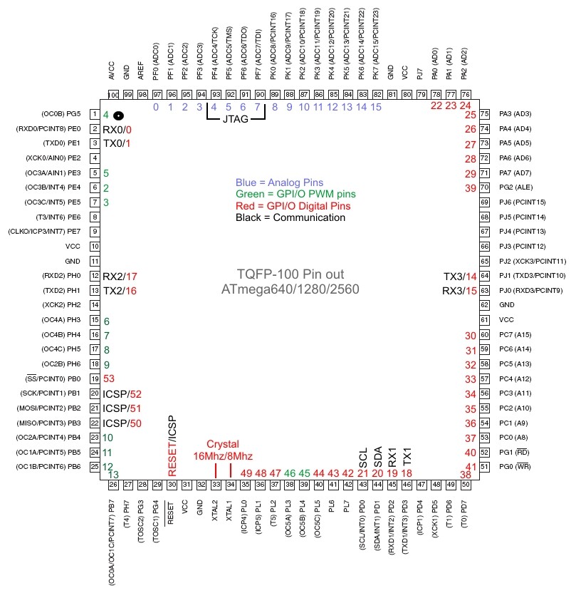
looking more at your diagram. Should pin 44 be green?
I thought that as well but in testing I could not get it to act as one. Only High or Low.
If you can verify that pin 44 is in deed a PWM pin then I will change it, maybe I missed something or something in the bootloader file is set incorrect and needs to or has been corrected.
specifically:
Re: Arduino Mega PWM pins
Reply #6 - 18.01.2010 at 16:28:03 |
OK, i reply to myself:
It works!
I think it was forgotten to implement.
At least, if you make that change to the coming Version18 (didn't try with 17), whose Release candidate can be downloaded.
Just add
Code:
} else if (digitalPinToTimer(pin) == TIMER5C) {
// connect pwm to pin on timer 5, channel B
sbi(TCCR5A, COM5C1);
// set pwm duty
OCR5C = val;
Does it work without altering code of any sort? Can't test at the moment, but I don't think it does. At least not under Arduino 17, haven't tried with 18 yet and 19 is around the corner.
Sorry, I should have been clearer in the excerpt from the link that I quoted. in -17, the code fragment definitely needs to be added in order for pwm on 44 to work. it was clearer in the forum item I linked to. The hardware allows pwm. there was a code omission that left it incorrectly implemented.
I hope you have a large pad under the 7805, they get toasty at automotive voltages even at 1/3 of an amp.
Yep, there is a copper pad on the bottom side, plus you can see in the picture several additional threw holes to dissipate heat. Also the 7805 is place on the board edge for an easy clip on sink if needed.
Just a note, but I'm a bit behind. The web page for this will be up this week.
Also the 7805 is place on the board edge for an easy clip on sink if needed.
When an auto is running the battery voltage is usually around 16 volts. So 16-5 = 11volts X .3 amps, so 3.3 watts of power will have to be dissapated by the 7805. This will take a very large heatsink to prevent the 7805 from going into thermo protection shutdown mode.
When an auto is running the battery voltage is usually around 16 volts. So 16-5 = 11volts X .3 amps, so 3.3 watts of power will have to be dissapated by the 7805. This will take a very large heatsink to prevent the 7805 from going into thermo protection shutdown mode.
16 volts is a bit high, you'll be blowing light bulbs. normally it will be around 13.5 to 14.5 possibly reaching 15 if the battery is almost dead. Don't think I have ever seen an automotive alternator reach 16 volts on a charge. Once the battery is charged ,which don't take long, the voltage floats around 13 volts, but that is still 2.4 watts.
Ligthing LEDs and such so far - I haven't had any thermal shut down.
But if it is a concern, that is what the REG pin is for, to supply an external regulated voltage from something that is properly heat sinked or stepped down.
But thats good, I will take that into advisement before the final run and these are things I want stressed tested. I also would like to hear a possible solution.
I work with batteries such as these daily (mostly AGMs).
And it's correct, car batteries are not 12 volts. that is only the nominal voltage while under load - not being charged. Less than 12.2 volts indicates a dead battery.