There are several different shields that can be bought on the net. The shields that I bought from China had some errors.
I could not get the SD card to work. On the LCD module the connector was not working and the Touch Screen + TFT LCD + SD (billgps2010@163.com, design by JQT, 5/6/2012) had the SCK and SI switched.
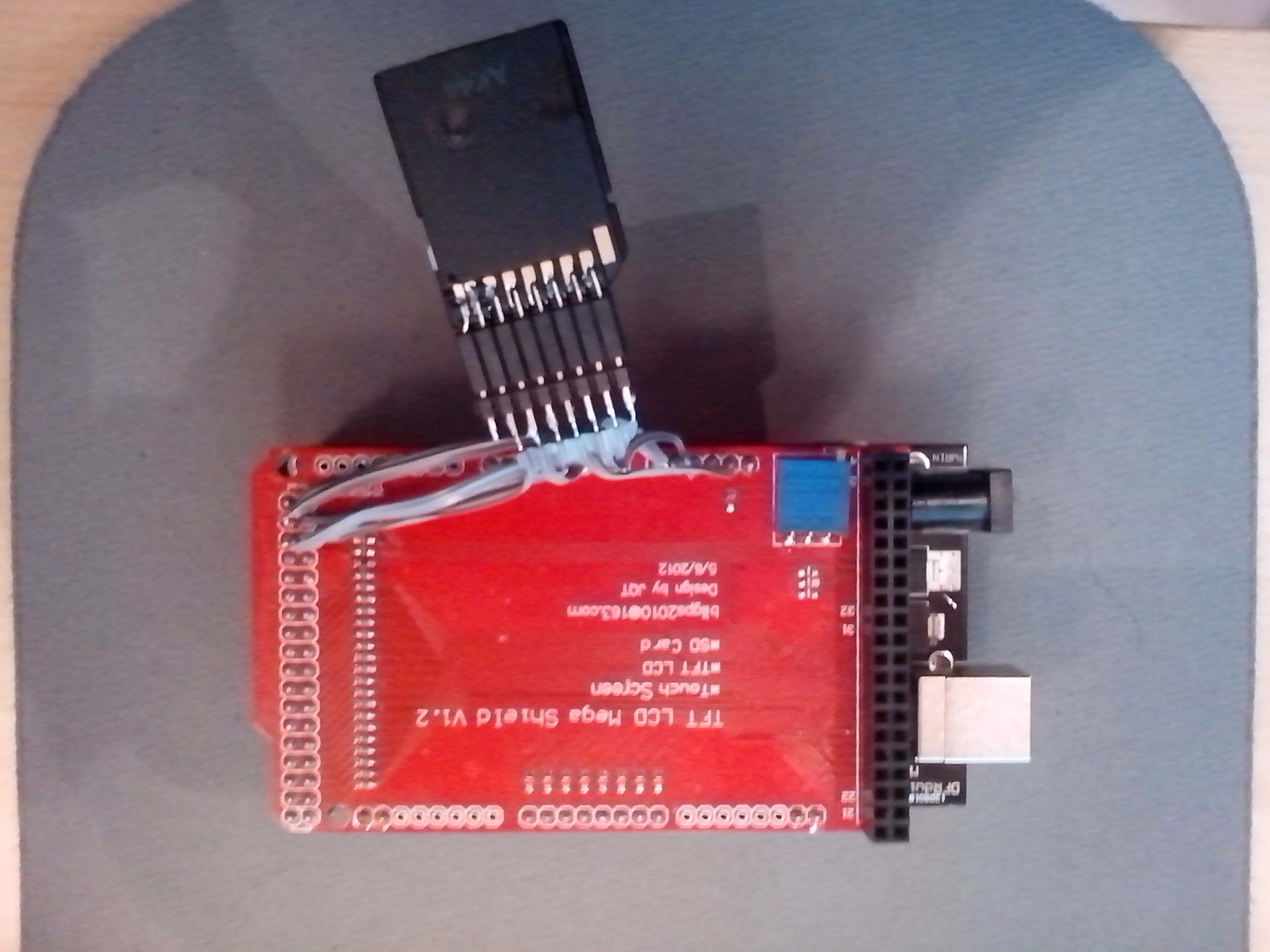
TFT LCD Mega Shield V1.2 with SD card connector is not working for SD card.
NOTE: The wiring or routing is wrong SCK and MOSI is switched on the Shield (red PCB).
The best approach is to solder and remove the resistors and the connector.
The setup is MEGA 1280 + TFT LCD Shield + 2.4" TFT Display with SD card slot.
NOTE: Remove the SD card connector & resistors on the display module (blue PCB).
SOLUTION:
Solder a new SD card connector to the SHIELD.
My setup is Mega 2560 + TFT LCD Shield (the same V1.2) + 3.2" TFT Display with SD card slot, and it seems to have the same SD problem.
I suppose the solution for my 2560 is exactly the same...
Few questions...
Do do made the connections directly without any resistors?
Its really necessary remove the sd card slot and resistors from the LCD module? Since it are not in use, don't think it made any difference in the modification of the shield. What do you think?
I could not determine where the resistors were connected. Due to lack of time and interest I decided to remove everything. The resistors are protecting the SD card from over-voltage but usually they are 5V resistant.
If you are sure you wire to the correct pin on the SD connector, just leave the resistors mounted. However, I believe it is easier and more reliable to solder directly to a pin rather to a SMD surface.
Conclusion: either way is good.