Hi,
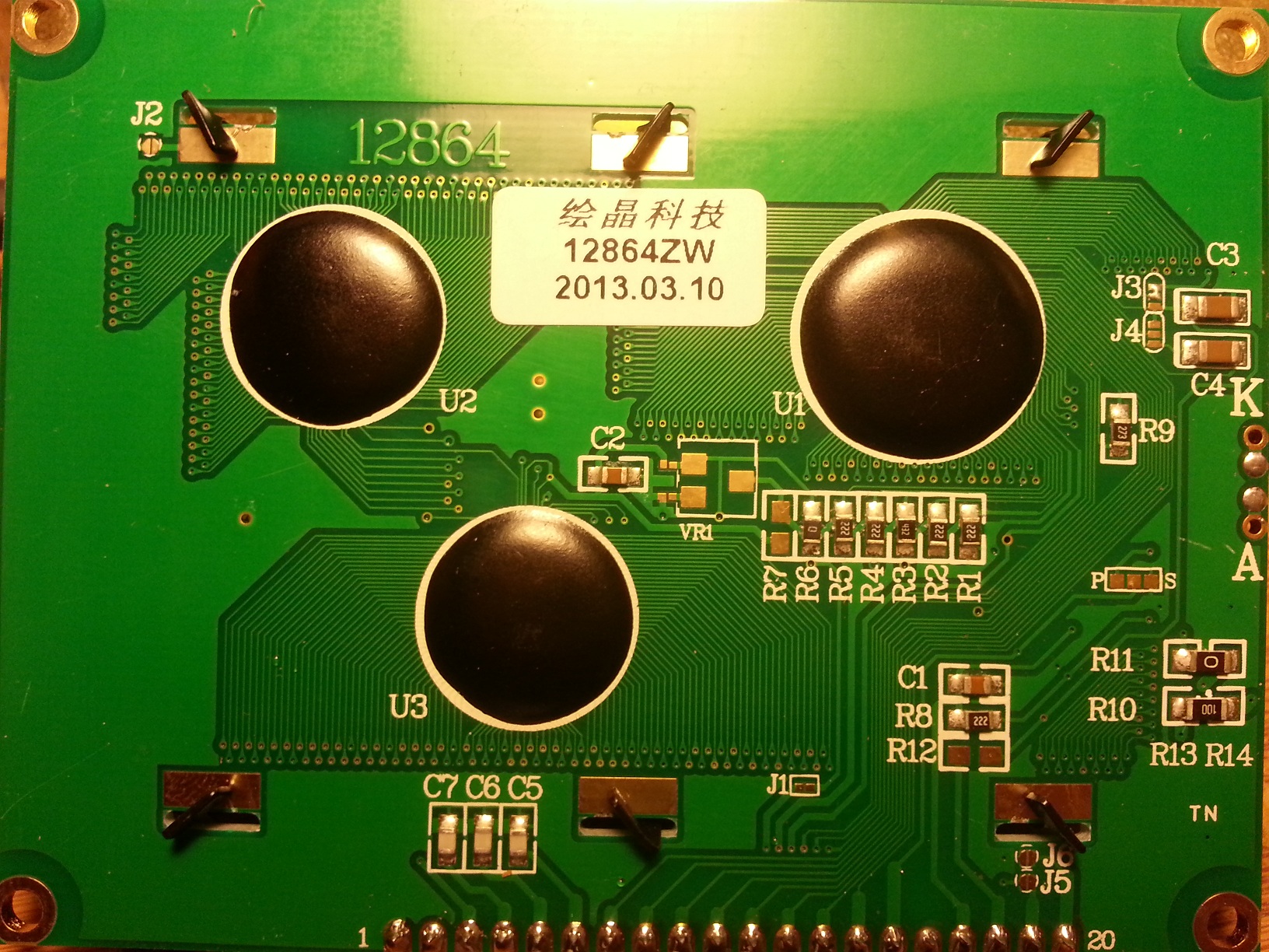
I cannot get a 128x64 display working. Given the markings on the back, "12864ZW", I believe the datasheet is this: http://www.digole.com/images/file/Digole_12864_LCD.pdf
Problem 1: can't set the contrast. Unfortunately the datasheet doesn't say how to do it. With a 10k VR wiper connected to the V0 pin, I've tried connecting the other VR pins to: VSS/VDD, VDD/VOUT, neither combination worked. They all give the same result as leaving V0 floating. So I presume contrast has been pre-set on the module.
Problem 2 (Main problem): No data I send to the module seems to do anything. The only way I can get any change in what's displayed is by holding the reset pin low or letting it float high. When I hold reset low, as per the photo, the whole screen is blue, I presume that means all pixels are off. When I let reset float high (or hold it high) as per the other photo, it seems all pixels are on (white). Being optimistic, to me this suggests at least that the contrast is adequately pre-set.
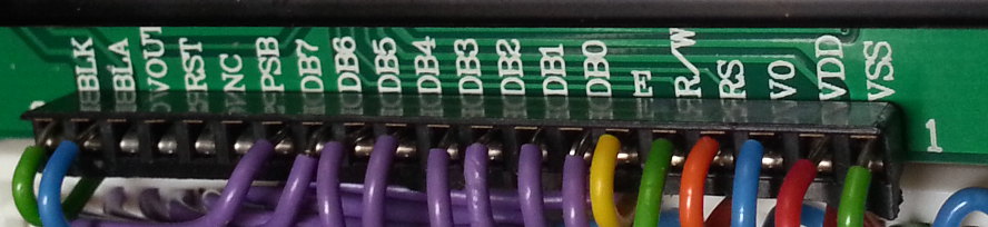
The pin connections I've used with the Arduino Nano is as follows:
LCD -> Nano
VSS (1) -> GND (12)
VDD (2) -> 5V (19)
V0 (3) -> NC
RS (4) -> D2 (11)
R/W (5) -> GND (12) (puts into write mode)
E (6) -> D3 (10)
DB0 (7) -> D4 (9)
DB1 (8) -> D5 (8)
DB2 (9) -> D6 (7)
DB3 (10) -> D7 (6)
DB4 (11) -> D8 (5)
DB5 (12) -> D9 (4)
DB6 (13) -> D10 (3)
DB7 (14) -> D11 (2)
PSB (15) -> float high (puts into parallel mode)
NC (16) -> NC
RST (17) -> D12(1)
VOUT(18) -> NC
BLA (19) -> 5V (19) via 470ohm resistor
BLK (20) -> GND (12)
The code I've used is as follows. I have used significantly longer delays than the datasheet specifies. I was hoping the least I'd get is either a blinking cursor, or for all pixels to turn off. Sadly absolutely nothing happens, I just get all pixels on, as if I hadn't sent any commands or data at all.
Please help! I'm at a complete loss here now. Thanks!
int RST = 12;
int RS = 2;
int EN = 3;
int DB0 = 4;
int DB1 = 5;
int DB2 = 6;
int DB3 = 7;
int DB4 = 8;
int DB5 = 9;
int DB6 = 10;
int DB7 = 11;
int LED = 13;
int ledOn = 0;

void setup() {
  initLCD();
}
void loop() {
}

void initLCD(){

  pinMode(RST, OUTPUT);
  pinMode(RS, OUTPUT);
  pinMode(EN, OUTPUT);
  pinMode(DB0, OUTPUT);
  pinMode(DB1, OUTPUT);
  pinMode(DB2, OUTPUT);
  pinMode(DB3, OUTPUT);
  pinMode(DB4, OUTPUT);
  pinMode(DB5, OUTPUT);
  pinMode(DB6, OUTPUT);
  pinMode(DB7, OUTPUT);

  digitalWrite(RST, 0);

  // ensure EN starts off low
  digitalWrite(EN, 0);

  // delay while screen resets
  delay(100);

  // come out of reset
  digitalWrite(RST, 1);

  // lcd start up time
  delay(100);

  // set 8 bit mode & basic instruction set
  send(0, 0, 0, 1, 1, 0, 0, 0, 0);
  delayMicroseconds(200);

  // do it again (as per datasheet flow chart)
  send(0, 0, 0, 1, 1, 0, 0, 0, 0);
  delayMicroseconds(100);

  // Display ON/OFF
  // 0, 0, 0, 0, 0, 1, DISPLAY, CURSOR, BLINK;
  // I have tried both of the following:
  // send(0, 0, 0, 0, 0, 1, 0, 0, 0);
      send(0, 0, 0, 0, 0, 1, 1, 1, 1);
  delayMicroseconds(200);

  // Display Clear
  send(0, 0, 0, 0, 0, 0, 0, 0, 1);
  delay(20);

  // Entry mode set
  //   0, 0, 0, 0, 0, 0, 1, I/D, S
  send(0, 0, 0, 0, 0, 0, 1, 0, 0);
}

void send(
  byte rs,
  byte d7, byte d6, byte d5, byte d4,
  byte d3, byte d2, byte d1, byte d0){

  digitalWrite(RS, rs);
  digitalWrite(EN, 1);
  digitalWrite(DB7, DB7);
  digitalWrite(DB6, DB6);
  digitalWrite(DB5, DB5);
  digitalWrite(DB4, DB4);
  digitalWrite(DB3, DB3);
  digitalWrite(DB2, DB2);
  digitalWrite(DB1, DB1);
  digitalWrite(DB0, DB0);

  // data setup time >40ns, enable pulse width > 160ns
  delayMicroseconds(1);

  digitalWrite(EN, 0);

  // data hold time >20ns
  delayMicroseconds(1);

  // enable cycle time > 1.8delayMicroseconds
  delayMicroseconds(10);
}
Edit note: I have added reset code and wiring since taking the photos. Now reset is held low while EN is set low, just in case the LCD was picking up erroneous data as the pins were initialised. However, the problems remain.


