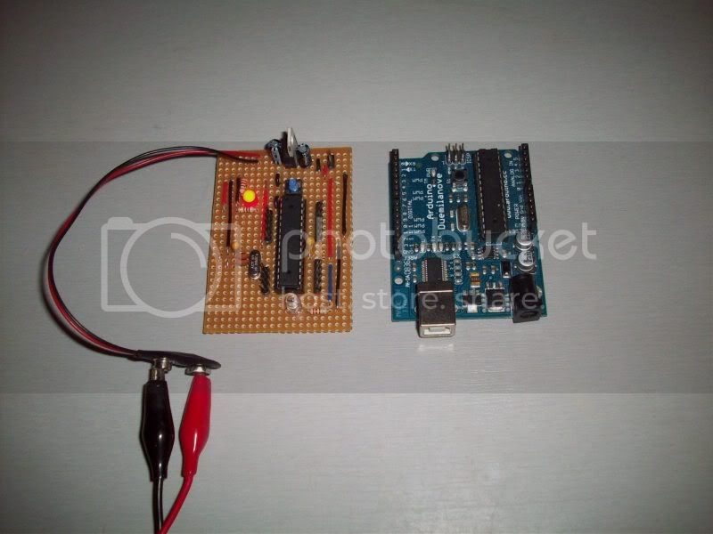
This was only started tonight, so would love to hear how other's would go about improving it, Im just working out a few options for ICSP and cutting up some strips of pins to make it a little more practical then having to solder your I/Os to the board.
If you want to make this make sure you refer to the Arduino Pin Map when hooking up your connections:
Woot, I like the male pin idea! I've got a setup on a breadboard right now, pretty much the same setup!
I'm curious though, Retrolefty, what's the difference between connecting Aref and, well, not? (I'm fairly new, so sorry if this seems ignorant:D)
I followed the tutorial Tom Igoe made and in the breadboard setup he used, he connected the Aref to power. http://itp.nyu.edu/physcomp/Tutorials/ArduinoBreadboard
But regardless! Looking good Noob (haha:D) Your solder job looks pretty good, I need to practice more! Good job!
I'm curious though, Retrolefty, what's the difference between connecting Aref and, well, not?
It's somewhat technical and one really needs to read the AVR data sheet as the whole analog reference section is a little complex but has a lot of flexibility. Basically the way the Arduino core software sets up analog reference voltage could result in damage if you have +5vdc wire to the AREF pin and execute the wrong internal command changing the reference set-up. Bottom line, leave AREF disconnected unless you have researched it's proper use.
Nice job, I also run similar format stripboad layouts so as to keep my Duemilanove ready for quick prototyping or to use when trying some electronically 'dubious' setups. :-?
I would be very careful with that interface (actually I would never use it!). It's a very old posting and has errors (that are mentioned in it) and omissons (like no power wiring shown for the hex invertor chip) and requires a RS-232 comm port which many modern PCs don't provide anymore.
A serial interface based on a MAX232 type RS-232 to TTL convertor is much more commonly used these days, if you indeed have a RS-232 comm port on your PC. There are also plently of USB to TTL convertor cables or modules that make it very simple to add programming capablility to your standalone set-up, like this example:
n00b - I've taken the liberty of dumping your list on the playground page I started back in Feb for UK suppliers of parts for a standalone Arduino : Arduino Playground - UKStandaloneParts
Maybe someone (maybe me) will come along and tidy it up.
I just wanted to note something.
On your component image, you are marking the capacitors with a circle. Since these are electrolytic, you should mark them with a strike through line to indicate their polarity. I had to check your actual board to be able to check the polarity fast.
And just an idea.
How about some "shields" on strip board as well?
You already have the male headers.
You just need to design some removable daughterboards with female headers on their down side.
f.e. for the serial to usb programmer.