Adafruit motor controller & Arduino Mega ADK w/USB - reroute pin 7 in software??

I have an Arduino Mega ADK and would like to make use of the motor shield and the USB port on the Mega ADK for my project. I would like to use the motor controller to drive DC motors on an OWI 535 arm, like I saw on an instructable:

I opened up AFMotor.h and AFMotor.cpp hoping I could just change a pin number, but it looks more complicated than that, as the code was written for the machine, not a n00b programmer like me.
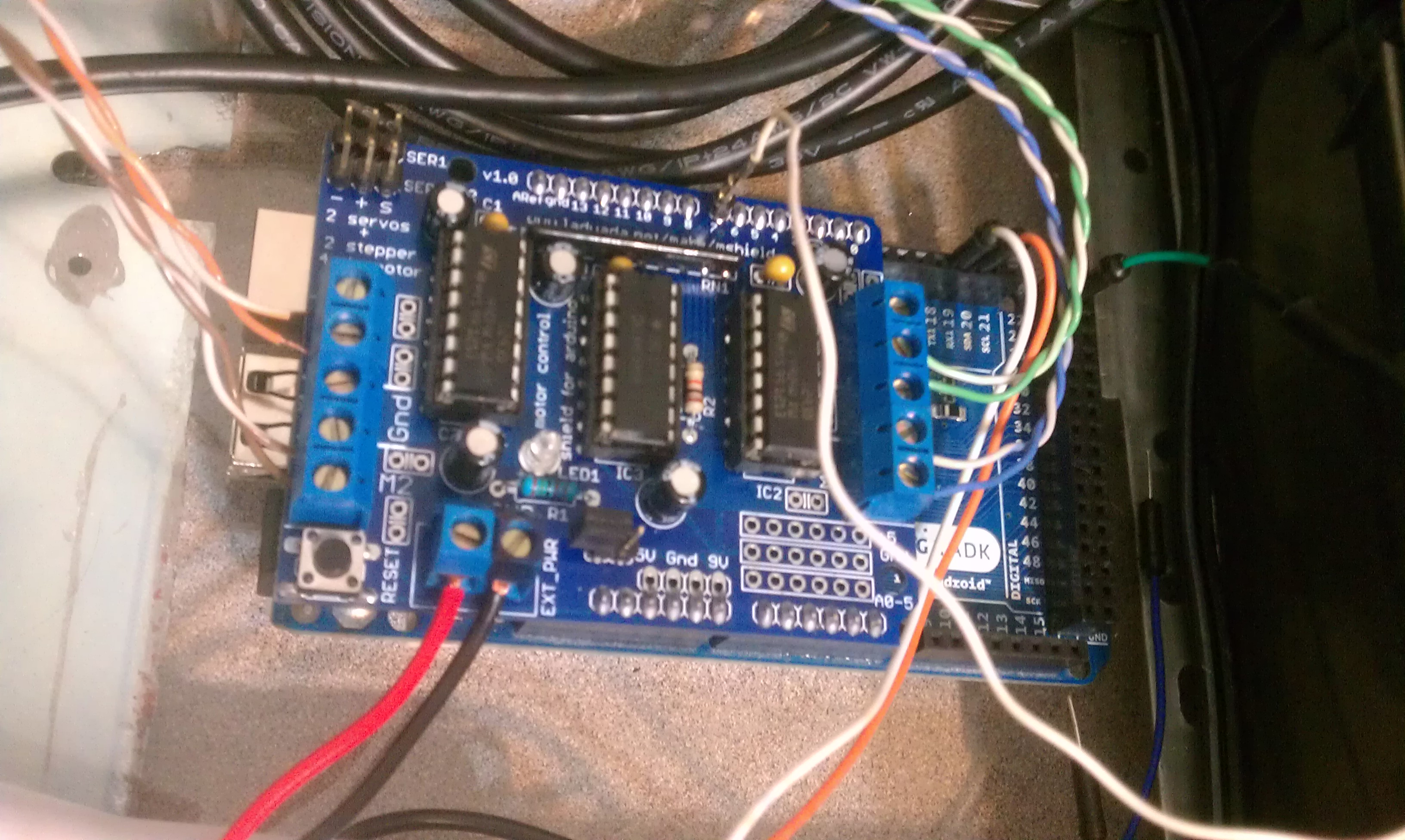
I have this board:
http://www.ladyada.net/make/mshield/
and this arduino:

This is why I need to move pin 7 (from Arduino main page):

USB Host: MAX3421E. The MAX3421E comunicate with Arduino with the SPI bus. So it uses the following pins:

Digital: 7 (RST), 50 (MISO), 51 (MOSI), 52 (SCK).
NB:Please do not use Digital pin 7 as input or output because is used in the comunication with MAX3421E
Non broken out on headers: PJ3 (GP_MAX), PJ6 (INT_MAX), PH7 (SS).

Is moving around pin 7 in code even possible? If so, is it feasible? it looks to me like it's kind of important and would be hard to move or replace. I did try to head this off at the pass by looking up pin numbers and all, but it seems I missed this one. Thankfully I found it before I started trying to get everything working.

The project is an OWI 535 arm on a roomba, and there will be an onboard android phone. Since I'm still testing, the USB is used for bluteooth, and I'll bring the Android in later.

I also posted in the Adafruit forums, but the first response I got was that the board wasn't an Adafruit board because I bougth it on Amazon and I should leave that forum and seek help elsewhere :-/ I don't know where that will go, so I decided to cross pollinate here:

http://forums.adafruit.com/viewtopic.php?f=31&t=35449

Pics of the board and the project:
https://www.facebook.com/media/set/?set=a.10151351037400498.519898.720010497&type=1&l=6e6e410d9c

Adafruit says they don't use SPI, so that means once I figureout or get help witht he code, it should be fine to reroute the pins functions to another pin. However it's not clear to me on how to do that.

In AFMotor.h, I find a reference to pin 7:

    // Arduino pin names for interface to 74HCT595 latch
    #define MOTORLATCH 12
    #define MOTORCLK 4
    #define MOTORENABLE 7
    #define MOTORDATA 8

In looking at both AFMotor.h and AFMotor.cpp that's the only reference that I can see. However, I see a lot of code written at a very low level, which I can't really read all that well. I do recognize that timers are being used, which doesn't make sense to me, as all the pins used have hardware PWM and shouldn't need software PWN using timers (do I have that right?).

I'm not sure this would be the only place to change it. I can't tell if this is for DC motor use or steppers. I'm not using stepepr motors, so I thought about ripping out all the code meant for steppers and other arduinos to see if I could improve readability.

Their code is available here:

I'm trying to get help on their forum but they keep insisting I don't have a "real" adafruit board and don't seem to be interested in helping me. As far as I can tell the thing is real, it even has their URL printed on the board.

What you will need to do is:

  1. Break the connection from the motor shield to digital pin 7 of the Arduino. The easiest way to do this is to cut off that pin on the bottom of the motor shield.

  2. Connect that pin on the motor shield to an unused pin, for example pin 13 or one of the analog pins. You can do this by connecting a jumper between pin 7 and your chosen pin on the top of the motor shield.

  3. Modify the motor shield software to redefine MOTORENABLE as your chosen replacement pin.

I think I've hit a road block. The code I mentioned before in the .h file

#define MOTORENABLE 7

doesn't appear to have any mention of pin 7 or MOTORENABLE anywhere else in the .h file.

Going to the .cpp file and I only find a few references to MOTORENABLE, the final one being to set it LOW and keep it there.

void AFMotorController::enable(void) {
  // setup the latch
  /*
  LATCH_DDR |= _BV(LATCH);
  ENABLE_DDR |= _BV(ENABLE);
  CLK_DDR |= _BV(CLK);
  SER_DDR |= _BV(SER);
  */
  pinMode(MOTORLATCH, OUTPUT);
  pinMode(MOTORENABLE, OUTPUT);
  pinMode(MOTORDATA, OUTPUT);
  pinMode(MOTORCLK, OUTPUT);

  latch_state = 0;

  latch_tx();  // "reset"

  //ENABLE_PORT &= ~_BV(ENABLE); // enable the chip outputs!
  digitalWrite(MOTORENABLE, LOW);
}

Based on the FAQ it seems there is some serial data going on:

Digital pin 4, 7, 8 and 12 are used to drive DC motors and Stepper motors via the 74HC595 serial-to-parallel latch
All these pins are in use if any DC motors or steppers are used

so based on the SPI page

and the Arduino Mega ADK page

that pin is a RST function, which I presume to be a shortened form of Reset. I couldn't find any mention of that on the SPI page though, save the pic of a header, so I'm not sure what to think of that.

and one line specific for every device:
SS (Slave Select) - the pin on each device that the master can use to enable and disable specific devices.

I'm thinking it might be the slave select line for the SPI, but that doesn't make much sense either. If it is that simple, pin 7 is not required and it would be easy to change the definition and that would be the end of it, compatibility problem solved.

But I saw a lot of loops and things that might not take into account the referenced pin numbers, so I will keep thinking this through.

dc42:
What you will need to do is:

  1. Break the connection from the motor shield to digital pin 7 of the Arduino. The easiest way to do this is to cut off that pin on the bottom of the motor shield.

  2. Connect that pin on the motor shield to an unused pin, for example pin 13 or one of the analog pins. You can do this by connecting a jumper between pin 7 and your chosen pin on the top of the motor shield.

  3. Modify the motor shield software to redefine MOTORENABLE as your chosen replacement pin.

Yes, my thoughts exactly. I'm asking for help on part 3. Sorry if I didn't make that clear. I'm not convinced it's as simple as changing it in that one place... that seems too easy. FYI my guardian angle is some kind of cross between Murphy (of Murphy's law) and a giant sky-being with a giant magnifying glass with the light focused on me.

From the board schematic, I see that pin 7 is connected to the output enable pin of the 74HCT595 shift register that drives the motor controller chips. So it makes perfect sense that once the shift register has been cleared, it is set to LOW and left there.

So if Im interpolating what ur saying; it really is that easy? Sweet!

Success!! Thasnks for your help dc42!!

I flipped the pin for 7 upside down, changed that one value assignment, and ran a new wire and the sample code works!

Before I did this I tested the board on an arduino uno since I did hear back from the guy on amazon and he said sometimes the chips come fried. It worked pretty good on the uno, better than with the shield being stock on the mega adk.

The first pic is the stack of boards in the roomba bay, the second is just the flipped pin with a wire coming off of it. I pulled out a wire from an old CDROM audio cable. Guess I need some female to male jumpers in my kit now, eh?