I am planning my next move on SMD parts. This time the ATMEGA32U4 chip that is featured on Arduino Micro, Leonardo, and Sparkfun micro pro. I'm reading Arduino's design right now. Found a few features that I'd like to understand. So the following is what I think they do. I'm sure I'm mistaken here and there so throw some truth at me please! Thanks.
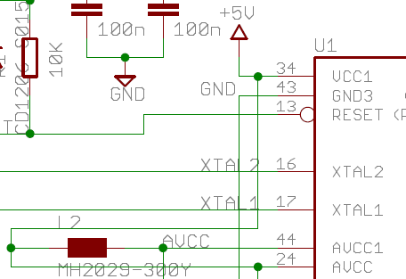
One of the pins is marked as PE2, top left, or pin 2 on port E. PE2 that is connected to GND via 10K ohm resistor on bottom right. According to Doc7766: (HWB) ? (Hardware bootloader activation). I bet this pulled to ground enables bootloader, right? I am still reading the Doc7766.
There is an interesting part on AVCC1 and AVCC, bottom left. The part MH2029-300Y between 5V and AVCC1 is an EMI bead. I bet it reduces interference on the supply so ADC can receive cleaner power, am I right? Oh, there is also a capacitor to GND that I missed.
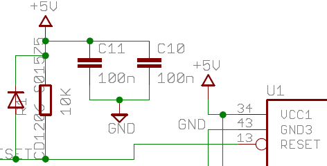
There is a diode pointing from RESET to 5V. See the far left side of the diagram. What does it do?
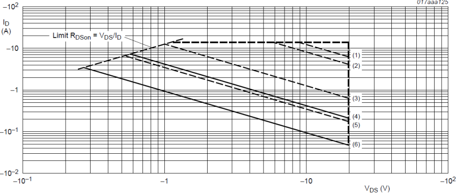
There is a part between VIN and the 5V voltage regulator, left side, PMV48XP. It’s a P-type MOSFET enhancement mode. I guess it is only on if the voltage at VIN is positive compared with GND and be a small threshold amount, so it will turn on while +5V is near GND. It will continue to stay on as long as VIN is that much more positive than 5V, so reverse power supply protection, am I correct? According to data sheet from NXP, when VDS=-1V, ID=-1A. See solid line for DC supply at 25 deg C. So at full on there is a 1V drop. This means we are taking away up to 1V from the VIN before it is applied to the 5V regulator, right?
I'm probably the last person who should be commenting here but since I just did a 32u4 board I do know a few answers:
There is an interesting part on AVCC1, bottom left. The part MH2029-300Y between 5V and AVCC1 is an EMI bead. I bet it reduces interference on the supply so ADC can receive cleaner power, am I right?
That's all I know... you do ask some good questions. I know I did my own bootloader from source (to change the vendor and product Id's plus I refused to continue the perversion that is the reverse-wired USB activity LEDs) and I'm having issues with auto-reset: It doesn't. I have to press the reset switch twice to upload code.
But I did start with the stock "LilyPad USB" bootloader and the auto reset did work, so I don't think you need the 10k resistor on HWB (I read somewhere about switching baud rates being part of the auto reset process) but I could certainly be wrong.
Thank you Brad. After seeing your board, I was hoping that you would jump in and help me. Good reference. I might consider adding a resistor as well and I missed that capacitor.
I don't know too much about bootloaders. Does the micro have its own bootloader? If yes, then why are you using the lilypad USB bootloader? I might be asking the obvious here.
Your name sounds familiar somehow. I don't know why.
liudr:
I don't know too much about bootloaders. Does the micro have its own bootloader? If yes, then why are you using the lilypad USB bootloader? I might be asking the obvious here.
Well... not the Arduino Micro (I don't think; from the contents of the bootloader/caterina directory it looks like this is the same as the leonardo and Esplora).
The LilyPadUSB has it's own version and I assume that's because it's 8MHz.
I started with the LilyPad USB bootloader because I'm also running at 8MHz
I'm building a bootloader from source because I hope to sell my board and while the firmware is Open Source, the USB Vendor and Product ID(s) are not. So you need to supply your own vendor Id and two product Id's (which means recompiling the source).
Your name sounds familiar somehow. I don't know why.
I think we've exchanged mails/posts in years past perhaps?
The diode prevents the reset pin voltage from rising (much) over 5V. Anything higher, and the diode shunts it back to the 5V rail voltage.
This is to designed to prevent the AVR accidently going into HVP (high-voltage programming) mode by a transient high voltage on the reset pin. So you can consider it a form of over-voltage protection.