OK, so I ran the blinking LED code and I got it to work.
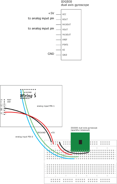
I also, ran an example code for the gyroscope:
/*
Sample code for the gyroscope
*/

// analog Pin 0 has the x output on the gyroscope connected to it
// analog Pin 1 has the y output on the gyroscope connected to it
// Name it:

int x, y;

void setup()
{
  Serial.begin(9600); // sets the serial port to 9600
}

void loop()
{
  x = analogRead(0); // read analog input pin 0
  y = analogRead(1); // read analog input pin 1
  Serial.print("rotational rates are x, y: ");
  Serial.print(" "); // prints a space between the label and the first number
  Serial.print(x, DEC); // print the rotational rate in the X axis
  Serial.print(" "); // prints a space between the numbes
  Serial.print(y,DEC); // print the rotational rate in the Y axis
  Serial.print('\n'); // prints on the next line
  delay(500);
}
This is what I got:
rotational rates are x, y: 270 272
rotational rates are x, y: 270 272
rotational rates are x, y: 269 267
rotational rates are x, y: 272 272
rotational rates are x, y: 275 275
rotational rates are x, y: 251 273
rotational rates are x, y: 257 273
rotational rates are x, y: 255 271
rotational rates are x, y: 267 270
rotational rates are x, y: 304 271
rotational rates are x, y: 270 282
rotational rates are x, y: 270 285
rotational rates are x, y: 270 279
rotational rates are x, y: 272 267
rotational rates are x, y: 274 254
rotational rates are x, y: 268 253
rotational rates are x, y: 271 286
rotational rates are x, y: 265 274
rotational rates are x, y: 253 273
rotational rates are x, y: 271 273
rotational rates are x, y: 272 272
rotational rates are x, y: 282 274
rotational rates are x, y: 270 272
rotational rates are x, y: 269 271
rotational rates are x, y: 264 271
rotational rates are x, y: 254 265
rotational rates are x, y: 277 278
rotational rates are x, y: 267 269
rotational rates are x, y: 270 270
rotational rates are x, y: 270 272
rotational rates are x, y: 309 275
rotational rates are x, y: 284 276
rotational rates are x, y: 285 270
rotational rates are x, y: 295 269
rotational rates are x, y: 260 275
rotational rates are x, y: 279 273
rotational rates are x, y: 297 274
rotational rates are x, y: 269 271
rotational rates are x, y: 225 276
rotational rates are x, y: 269 272
rotational rates are x, y: 270 272
rotational rates are x, y: 279 273
rotational rates are x, y: 301 276
rotational rates are x, y: 267 271
rotational rates are x, y: 270 273
rotational rates are x, y: 275 272
rotational rates are x, y: 280 262
rotational rates are x, y: 274 271
rotational rates are x, y: 270 272
rotational rates are x, y: 274 266
rotational rates are x, y: 272 270
rotational rates are x, y: 268 273
rotational rates are x, y: 267 272
rotational rates are x, y: 269 271
rotational rates are x, y: 227 268
rotational rates are x, y: 255 273
rotational rates are x, y: 271 270
rotational rates are x, y: 270 273
rotational rates are x, y: 225 274
rotational rates are x, y: 271 273
rotational rates are x, y: 272 279
rotational rates are x, y: 271 269
rotational rates are x, y: 264 297
rotational rates are x, y: 270 272
rotational rates are x, y: 271 271
rotational rates are x, y: 250 208
rotational rates are x, y: 260 237
rotational rates are x, y: 268 278
rotational rates are x, y: 261 265
rotational rates are x, y: 265 285
rotational rates are x, y: 268 258
rotational rates are x, y: 296 294
rotational rates are x, y: 213 277
rotational rates are x, y: 305 266
rotational rates are x, y: 216 281
rotational rates are x, y: 314 352
rotational rates are x, y: 272 260
rotational rates are x, y: 304 288
rotational rates are x, y: 251 272
rotational rates are x, y: 269 250
rotational rates are x, y: 320 277
rotational rates are x, y: 262 249
rotational rates are x, y: 250 273
rotational rates are x, y: 304 303
rotational rates are x, y: 235 217
rotational rates are x, y: 274 278
rotational rates are x, y: 256 253
rotational rates are x, y: 347 306
rotational rates are x, y: 220 291
rotational rates are x, y: 240 239
rotational rates are x, y: 289 267
rotational rates are x, y: 265 274
rotational rates are x, y: 272 278
rotational rates are x, y: 286 262
rotational rates are x, y: 259 263
rotational rates are x, y: 273 267
rotational rates are x, y: 267 277
rotational rates are x, y: 257 237
rotational rates are x, y: 253 285
rotational rates are x, y: 367 253
rotational rates are x, y: 257 276
rotational rates are x, y: 222 280
rotational rates are x, y: 271 273
rotational rates are x, y: 270 271
rotational rates are x, y: 263 299
rotational rates are x, y: 271 271
rotational rates are x, y: 270 272
rotational rates are x, y: 266 264
rotational rates are x, y: 269 272
rotational rates are x, y: 275 263
rotational rates are x, y: 270 271
rotational rates are x, y: 271 272
rotational rates are x, y: 267 279
rotational rates are x, y: 275 256
rotational rates are x, y: 270 272
rotational rates are x, y: 271 271
rotational rates are x, y: 315 375
Is this whats supposed to be happening or is something wrong with the code?
For the accelerometer, I was looking and that schematic is right. Thats the schematic for it if I wanted to use it in SPI mode. After doing some research , I found out that SPI is faster than I2C. Which do you think would be better to use in this case?