An LED bar graph tachometer

I want to build a simple LED bar graph tachometer. Maybe 10-12 LED's, green, yellow and red. Maybe an orange thrown in there :smiley:

The "redline" will only be 4500-5000 RPM.

Perhaps 1000rpm= 2 lit, 2000rpm= 3 lit, 2500rpm= 4 lit, etc.

I've been tinkering with practice code making led's blink and stay lit plus some sequencing so the hardware side won't be much trouble. Plus, I'm finding that I'm A LOT more into the BUILDING over the PROGRAMMING sigh Hopefully this will change as I become more proficient (And less confused) by it...

I have an IR receiver and emitter set so I would like to start with using that for a trigger but I've ordered a couple of hall-effect sensors and magnets for the final build.

This will be my first project involving both input and output so it should be a good learning experience!

Any guidance would be most welcome!

Sounds like a fun project,
you should post your code so people can see how you are trying this so we can offer specific examples and help,
what kind of hall sensors did u order? There are ones that are ratiometric and you get an analog signal and there are more switch type ones that the output is considered digital( high or low)
for rpm you are best of with the digital because its alot faster to do a digital read than analog read and some math

http://arduino.cc/playground/Main/ReadingRPM

Paco

I ordered 10 of these:

http://www.melexis.com/prodfiles/0003715_hallapps.pdf

It seems that all the examples I can find seem to use serial output to read RPM. I'm looking for a way to illuminate a bank of LED's based on RPM.

It's complicated (at least to me :roll_eyes:) because the output to the LED's will have time factored in. Damned if I can find a suitable code example.

I'm leaning towards something like:

if input to pin (X) = 1000 times a minute , output to pin (Y) hi,
if input to pin (x) = 2000 times a minute , output to pin (Y) and (Z) hi
if input to pin (X) = 3000 times a minute , output to pin (Y) and (Z) and (A) hi

(This is just my crude example of the logic I believe would be necessary :blush:)

I'm sure there would be some additional coding for I/O when the motor slowed down or else it would just "hold" the lamps on.

It would be great to find some code already written that would allow me to just change some parameters for tuning.

The learning curve is pretty steep for me but it would be sweet to actually build something useful.

First start to read the hall sensor(s) value, calculate and write the output value to the serialmonitor. A challange enough to start with as newbie.
Use a simpel electro motor first.
When this works then start to work on the display of the RPM by leds.
Search the forum here for RPM projects.

Paco

Thanks.

I found this:

http://arduino.cc/forum/index.php/topic,94690.0.html

And managed to get it running and printed to the serial monitor. I'm getting value changes as I shade the detector. Still not sure what to do with it though. It'll probably be a few weeks before my mail order stuff comes in...

Update before bed...

I found this:

http://www.me.umn.edu/courses/me2011/arduino/technotes/irbeam/irbeam.html

And set it up without much fuss. Now I have 1 or 0 when I break the beam. Won't a hall effect sensor work the same way? I figure I'll start by making an LED blink or something when the beam is broken. Should be a good start point...

I managed to get this working:

/*---------------------------
IR beam demo
----------------------------*/
#define LED 2
#define BEAM 4
byte i;
void setup()
{
  pinMode(LED,OUTPUT);
  pinMode(BEAM,INPUT);
  digitalWrite(LED,LOW);
}
void loop()
{
  digitalWrite(LED,digitalRead(BEAM));
}

It's pretty basic but it seems like a good start point...

Pretty basic is the best place to start
once you get the hang of the basics you can start altering examples or making your own that does exactly what you want it to, just make sure you pay attention to how things work in those examples

That is a cool project.

If I where you, I will split the project in two parts.

Part One : Code testing using a 555 , wired it into a variable frequency generator or use a frequency generator.

Convert RPM --> Frequency

For display, I will use a 2 X 74HC595 or 1 X MAX7219 or use the digital pins ( you are a bit limited ) .

Bear in mind, the coding and wirring for display will be different for each methode use.

Get that working first.

Here a pseudo code :

RPM sample  Frequency  -- > RPM

Calculate a value to be display RPM --> numbers of leds  OR 

Frequency --- > numbers of leds to display

Figure first : 1 segment - led  = what is the value in RPM / Frequency 

Example : 100 RPM = one segment on  - data = 00000001
               200 RPM = 2 segment on   - data = 00000011
               300 RPM = 3 segemnt on  - data = 00000111
               400 RPM = 4 segment on - data = 00001111
               the rest...

Display the leds.

Part two :

The circuit to sample the RPM and connect with the code and display circuit.

Anyway, that is my 2 cent idea

Hall sensor, mechanical switch or optical sensor will all have the same result..... 0 or 1 as take up sensor.
Like Winner said start small and understand what your doing.
Copy and paste is not always the best way to learn I found out too as newbie in this world.

Here a link to an LCD project http://arduinoprojects101.com/arduino-rpm-counter-tachometer/

Paco

Hint: The RPM will amost never be exactly 100 or 2000 RPM If you want a "bar-graph", you can say if >= 1000 RPM (greater than OR equal to). If you want a "dot" display, you can turn-on the LED if it's greater than 1000 AND less than 1500, etc.

I'm sure there would be some additional coding for I/O when the motor slowed down or else it would just "hold" the lamps on.

Just put your code in a loop, so that it checks & updates as fast as it can. Or, if that makes the display too "jumpy", you can hold the loop for 10th of a second or so before looping. If you wanted, you could hold the top LED a bit longer, or freeze it 'till you hit a "reset" button, etc. Or, hold longer if you go over the redline, etc.

Thanks for the helpful input!

I thought about rigging up a pulse generator to aid with code testing but I decided on building a test mule similar to the final deal:

Looks like a weird lathe :roll_eyes:

It's a 12V DC motor with a slotted disc for breaking the IR beam. It's kind of hit and miss with reading the input. The serial monitor shows the occasional double 1 or zero. I'm not sure what's going on there. I'm hoping it will suffice for working out some of the details before my hall effect sensors get here. Hopefully any success I have will be applicable to the HE sensor setup.

I rigged up a pot and a mosfet to control the motor speed. I don't have a big range of speeds though... but it looks like enough to work with for prototyping.

I have the "Programming Arduino" book so hopefully I can get something written from scratch. I'm more of a "builder-O-crap" than a computer programmer but maybe I can get something cooking.

When I was testing the IR stuff I noticed that the detector output just BARELY dropped below 2.5 volts so maybe that has something to do with my spotty triggering.

Well, I have almost all the hardware built:

I still need to put some resistors on the led's and wires from them to the pins.

Guess I need to figure out how to code it...

If you get fed up with the breadboard and want a more durable solution, what you have there is doing pretty much what a standard LED bar shift light does. They aren't terribly expensive. I know it's not as much fun, but if you're after a working solution rather than a fun project then you might want to bear that in mind.

I could buy one but I like building crap! Here's where I am:

I'm using the UNO to vary the speed of the motor and a Propeller board is reading IR sensor and running the LED's. I'm still stumped on the code for getting the bar graph to work. I figure it's a start though...

hoff70:
I could buy one but I like building crap!

Understood! :slight_smile:

I'm not clear what those LEDs are doing yet - have you got the frequency detection logic working yet? You don't need the LEDs working to test that, you could simply print out the values and confirm it's measuring the speed correctly.

The IR beam is just triggering the LED pins ON/OFF. I get a blink each time a hole in the disc comes around. It's actually not doing much but I wanted to start by having the IR beam trigger some kind of output...

I need to figure out how to have the chip calculate RPM based on the pulses over a given time and output to different blocks of pins based in that info. I think...

Well, you need to measure or calculate the RPM, certainly. If you have an input that is pulsing once per revolution, measuring RPM is just a matter of timing or counting those pulses.

Outputting the RPM value on your LEDs is an unrelated and much easier problem.

Yep, 1 pulse per rev. I figure I need to sample it over time and then store that value and output it some way. I'm guessing the sample time will dictate how rapidly the display updates.

Well, I finally got the HE sensors in and figured out how to wire them up. Pretty neat little devices!

//-----------------------------------------------
 volatile byte rpmcount;
 unsigned int rpm;
 unsigned long timeold;
 void setup()
 {
   Serial.begin(9600);
   attachInterrupt(0, rpm_fun, RISING);
   rpmcount = 0;
   rpm = 0;
   timeold = 0;
 }
 void loop()
 {
   if (rpmcount >= 20) { 
     //Update RPM every 20 counts, increase this for better RPM resolution,
     //decrease for faster update
     rpm = 30*1000/(millis() - timeold)*rpmcount;
     timeold = millis();
     rpmcount = 0;
     Serial.println(rpm,DEC);
   }
 }
 void rpm_fun()
 {
   rpmcount++;
   //Each rotation, this interrupt function is run twice
 }
//-----------------------------------------------

I've been puttering with this code some and I imagine it holds the key to what I'm trying to accomplish.

Any hints, pointers? I'd like to get something sort of working this weekend.

Thanks.

I also found this:

At least I have input to the Arduino with an HE sensor...

Not much action here but I've been making baby steps:

//code by Crenn from http://thebestcasescenario.com
//project by Charles Gantt from http://themakersworkbench.com


/*To disable interrupts:
 cli();                // disable global interrupts

and to enable them:  
 sei();                // enable interrupts
*/


                                   //Varibles used for calculations
int NbTopsFan; 
int Calc;

                                  //The pin location of the sensor
int hallsensor = 2;
int ledPin = 4;           //$STUFF I ADDED$


typedef struct{                  //Defines the structure for multiple fans and their dividers
  char fantype;
  unsigned int fandiv;
}fanspec;

//Definitions of the fans
fanspec fanspace[3]={{0,1},{1,2},{2,8}};

char fan = 1;   //This is the varible used to select the fan and it's divider, set 1 for unipole hall effect sensor 
               //and 2 for bipole hall effect sensor 


void rpm ()      //This is the function that the interupt calls 
{ 
 NbTopsFan++; 
} 

              //This is the setup function where the serial port is initialised,
             //and the interrupt is attached
void setup() 
{ 
 pinMode(hallsensor, INPUT); 
 Serial.begin(9600); 
 attachInterrupt(0, rpm, RISING);
 pinMode(ledPin, OUTPUT);    ////$STUFF I ADDED$$
} 
void loop () 
{
   NbTopsFan = 0;	//Set NbTops to 0 ready for calculations
   sei();		//Enables interrupts
   delay (1000);	//Wait 1 second
   cli();		//Disable interrupts
   Calc = ((NbTopsFan * 60)/fanspace[fan].fandiv); //Times NbTopsFan (which is apprioxiamately the fequency the fan is spinning at) by 60 seconds before dividing by the fan's divider
   Serial.print (Calc, DEC); //Prints the number calculated above
   Serial.print (" rpm\r\n"); //Prints " rpm" and a new line
   
   //$STUFF I ADDED$/////////////////////////////////////////////////////////////////////////////
   if (Calc > 40)
   {
     digitalWrite (4, HIGH);
     delay (500);
   }
   if (Calc < 40)
   {
     digitalWrite (4, LOW);
   }
}

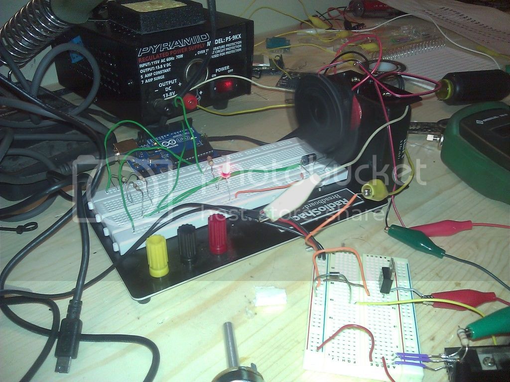
I didn't do much but I am getting serial output of RPM to the serial monitor and I'm getting a single LED to turn ON/OFF with RPM changes. My RPM measurement doesn't seem to be accurate but it is proportional so I figure I can tinker with the code to get it working. I guess the numbers really don't matter as long as I can get the output to register correctly. I'm not going to be using the serial data anyway.

I did get the hall effect sensor working after learning that I needed a resistor between the pos and signal :cold_sweat:

Just one sad little LED for output but it's a start:

No little magnets to mount on my test rig so I'm stuck waving a big one over the HE sensor for now... I considered using a PC fan 3rd wire for input but I want to stick with what I'm going to use in the final build so I don't complicate things.

Would someone mind explaining what's going on in the code? Especially this line:

fanspec fanspace[3]={{0,1},{1,2},{2,8}};

Thanks.

More stuff:

//code by Crenn from http://thebestcasescenario.com
//project by Charles Gantt from http://themakersworkbench.com


/*To disable interrupts:
 cli();                // disable global interrupts

and to enable them:  
 sei();                // enable interrupts
*/


                                   //Varibles used for calculations
int NbTopsFan; 
int Calc;

                                  //The pin location of the sensor
int hallsensor = 2;
int ledPin = 4;           //$STUFF I ADDED$
int ledPin1 = 5;
int ledPin2 = 6;
int ledPin3 = 7;

                        
typedef struct{                  //Defines the structure for multiple fans and their dividers
  char fantype;
  unsigned int fandiv;
}fanspec;

//Definitions of the fans
fanspec fanspace[3]={{0,1},{1,2},{2,8}};

char fan = 1;   //This is the varible used to select the fan and it's divider, set 1 for unipole hall effect sensor 
               //and 2 for bipole hall effect sensor 


void rpm ()      //This is the function that the interupt calls 
{ 
 NbTopsFan++; 
} 

              //This is the setup function where the serial port is initialised,
             //and the interrupt is attached
void setup() 
{ 
 pinMode(hallsensor, INPUT); 
 Serial.begin(9600); 
 attachInterrupt(0, rpm, RISING);
 pinMode(ledPin, OUTPUT);////$STUFF I ADDED$$
 pinMode(ledPin1, OUTPUT);
 pinMode(ledPin2, OUTPUT);
 pinMode(ledPin3, OUTPUT);
} 
void loop () 
{
   NbTopsFan = 0;	//Set NbTops to 0 ready for calculations
   sei();		//Enables interrupts
   delay (1000);	//Wait 1 second
   cli();		//Disable interrupts
   Calc = ((NbTopsFan * 60)/fanspace[fan].fandiv); //Times NbTopsFan (which is apprioxiamately the fequency the fan is spinning at) by 60 seconds before dividing by the fan's divider
   Serial.print (Calc, DEC); //Prints the number calculated above
   Serial.print (" rpm\r\n"); //Prints " rpm" and a new line
   
   //$STUFF I ADDED$/////////////////////////////////////////////////////////////////////////////
   if (Calc > 40)
   {
     digitalWrite (4, HIGH);
     delay (100);
   }
   if (Calc < 40)
   {
     digitalWrite (4, LOW);
   }
   if (Calc > 100)
   {
     digitalWrite (5, HIGH);
     delay(100);
   }
   if (Calc < 100)
   {
     digitalWrite (5, LOW);
   }
   //////
    if (Calc > 240)
   {
     digitalWrite (6, HIGH);
     delay(100);
   }
   if (Calc < 240)
   {
     digitalWrite (6, LOW);
   }
   /////
    if (Calc > 300)
   {
     digitalWrite (7, HIGH);
     delay(100);
   }
   if (Calc < 300)
   {
     digitalWrite (7, LOW);
   }


}

It's clunky but it seems to work!

Also, If all goes well, (And it looks like it very well may :)) I would like to do a permanent install. I don't want to use my UNO for it but rather build a bare bones chip setup. Any input on this? I suppose I would at least need a crystal as well as a power supply. Would be neat to (Try to) build!