2-bit PWM

Didn't quite know where to put this one!

After being inspired by the guys over at open music lab (Dual PWM Circuits | Open Music Labs), I had a quick look for nice quick and easy code, implementing their technique.

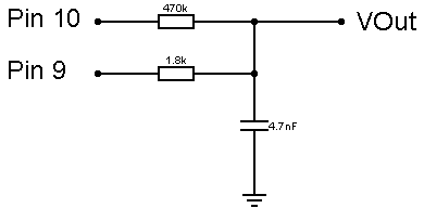
I had a quick search and didn't seem to find anything so I thought i'd have a quick go myself. I wrote it to use timer 1 and pins 9 and 10, at 31.25kHz and 16bit output. Since not all of us have precision resistors, take this example with a slight pinch of salt. I used a 1.8k resistor and a 470k resistor, if this was ideal, i'd being a 1.8k resistor and a 460.8k resistor but this value isn't available to the standard user! If less error is required, a 2.2k resistor and 560k resistor can be used, with perfect resistors, this should give about 0.56% error.

I wrote the code using direct timer and port manipulation for speed. Implementing a 10000-time for loop, and using micros (ensuring to divide the total time by 1.024 as 1micros-uS is = 1.024uS as far as i'm aware), I calculated the direct implementation to take about 1.23uS to execute. Changing all the instructions back to analogWrite and digitalWrite drastically increased execution time to 14.68uS, nearly 12x longer!

I will include a schematic of how to connect the resistors and capacitor. The low pass filter is set at about 18.8kHz.

Code:

long WriteVal = 32768; //Value to be written to output, needs to be long to support 16bit

void setup(){
  DDRB = DDRB | 0x18;   //Set pins 9 and 10 as outputs
  TCCR1A = _BV(COM1A1) | _BV(COM1B1) | _BV(WGM12) | _BV(WGM10);   //Pin 9 & 10, fast PWM wgm
  TCCR1B = _BV(CS10);   //Set prescaler to 1, 32.5KHz PWM freq
}

void loop(){
  if(WriteVal>255){
    PORTB = 0x10;   //Write pin 10 high, all other pins of B register low
    OCR1A = WriteVal>>8;   //Write output value bitshifted 8 to the right to pin 9
  }
  else if(WriteVal<256){
    PORTB = 0x08;   //Write pin 9 high, all other pins of B register low
    OCR1B = WriteVal;   //As output value will be <256, write it straight to pin 10
  }
}

As can be seen, its really simple and just includes some bitshifts and direct manipulation of registers. Using my multimeter, I can verify that with a wrote value of 32768, the voltage is 2.345v. The supply voltage being 4.69v states that with a value of 32768 (half way), the voltage should be 2.345v. This seems acceptable proof to me!

Kudos to Openmusiclabs for a brilliant article!

arduino 2bitpwm.png

as 1micros-uS is = 1.024uS as far as i'm aware

No it is not. 1mS is 1000uS. This is not binary measurements.

That link reminded me of marking a student essay, basically most of it is right, but often the wrong words are used and some of the fundamental understanding is wrong.
For example the 74HC14s are external buffers they are not switches. He talks about output resistance when he means impedance and says PWM is basically AM, which it is not. He talks about a negitave output where he means a 180 degree phase shift. He also seems obsessed with distortion said it were the only measure of quality.

There is no mention of monoticity which is the basic thing you need to preserve in any D/A conversion.

But does it sound good ?

A lot of people have been excited by/reposting this link, but has anyone used or seen it used as part of a synth yet ?

Duane B

But does it sound good ?

It is audio, good has many different meanings depending on what the audio is.

A lot of people have been excited by/reposting this lin

I am supprised at that, there is nothing new here as far as i know, it's all a bit of a kluge. I would have thought that what you gain I range you loose in lack of monoticity.

GM,
I thought I saw somewhere that you had been attending 'noise nights' so I would expect you of all people to be flexible on the definition of 'sound good'.

I am not sure that a standalone Arduino has the horsepower to really make practical use of 16bit PWM anyway - much bigger wave tables, more number crunching, more memory reads/writes etc.

Lets see if anyone comes up with a interesting working synth based on this.

Duane B

' so I would expect you of all people to be flexible on the definition of 'sound good'.

I am and that was my point, good covers a multitude of sins.
I will have a go at doing the thing properly and then see what it sounds like.

Hi,

With regards to the perception of audio quality, do you need to add 1-bit to double the perception of quality or do you need to double the number of bits to double the perceived quality ?

I am guessing the later, but if its the former I would be interested to try a 10-bit implementation of this -

At the moment, four 8 bit channels are downshifted into a single 8-bit output, It would be interesting to hear played through a 10-bit output without the down shifting.

GM, if you think it would be interesting to try from a hardware side, I will mod the code and send it over to you.

Duane B

rcarduino.blogspot.com

Grumpy_Mike:

as 1micros-uS is = 1.024uS as far as i'm aware

No it is not. 1mS is 1000uS. This is not binary measurements.

That link reminded me of marking a student essay, basically most of it is right, but often the wrong words are used and some of the fundamental understanding is wrong.
For example the 74HC14s are external buffers they are not switches. He talks about output resistance when he means impedance and says PWM is basically AM, which it is not. He talks about a negitave output where he means a 180 degree phase shift. He also seems obsessed with distortion said it were the only measure of quality.

There is no mention of monoticity which is the basic thing you need to preserve in any D/A conversion.

Hi there GM, thank you for the interest! My apologies on the microsecond business, I thought an arduino microsecond was derived from the division of the clock but I didn't realise that 16MHz was divisible directly down to 1uS! Either way though, the 12x speed different still stands.

As the values written to the PWM registers and ports are changed on each iteration of the loop, I can only assume that this filter is monotonic? As for the output to drop in voltage, the values being written to the PWM registers and ports would need to drop, theoretically they should both be directly proportional. On the other hand, testing in reality will give different results due to the variations in resistance. If the two resistors were exactly the value, this PWM method should be equivalent to a 16 bit PWM Output.

With regards to the perception of audio quality, do you need to add 1-bit to double the perception of quality or do you need to double the number of bits to double the perceived quality ?

It is far more complex than this. The problem is the "perception" bit. This is different for different people. I have mentioned before my favorite academic paper was entitled "The effects of alcohol on perceived quantization noise" Which had people give scores to how good they though sounds were with a given amount of quantization noise. Surprise surprise the more they had to drink the less bothered they were. They also tried it with horse race commentary and again they found that if people had a bet on the race they were less critical of any noise.
There are lots of factors in play here. From my own experience the 13 bits is very nearly as good as 16 bits.

I can only assume that this filter is monotonic?

Its not the filter, it is a function of the A/D. Basically it means that for every increment in the digital input the output has to increase or say the same. This is a problem when you are trying to make your own D/A with resistors that are not tight enough in the tolerance. This adds to the noise or distortion ( that link incorrectly thinks there is a difference in digital terms ). The way to do it properly is to replace a portion of the fixed resistor with a helical pot, and write some software to allow you to adjust the pot to the correct value. Then you only have to worry about drift of the output impedance of the output drivers.

Also having a capacitor on the summing junction is not a good idea. Yes it will form a filter but the break frequency will be different for the two different PWM sources because of the different values of resistors. Better to have the summing junction isolated with a buffer amplifier before applying the filter so that it is a constant response. In the end it all boils down to the transfer function.

But the most important thing is what context the sound is being generated in. Sounds can be too dirty or too clean and part of the joy of audio is that you can love both.

At the moment, four 8 bit channels are downshifted into a single 8-bit output, It would be interesting to hear played through a 10-bit output without the down shifting

I would suspect it would sound better by a factor of one eight better, but that is just a guess.

if you think it would be interesting to try from a hardware side, I will mod the code and send it over to you.

Yes I am going to do some more audio work soon but I have some Raspberry Pi stuff to finish writing first.

Just a plug:-
Have you seen my Raspberry Pi for Dummies book http://www.amazon.co.uk/Raspberry-For-Dummies-Computer-Tech/dp/1118554213

I just noticed a fatal error in my code! At the moment, its kind of like pseudo 16bit in the sense that it will have 8 bit resolution between 0 and 255, then 8 bit resolution between 255 and 65536.

This can be solved by changing the code to:

void loop(){
    OCR1B = WriteVal&255;   //Write the low 8 bits to pin 10
    OCR1A = WriteVal>>8;   //Write output value bitshifted 8 to the right to pin 9
}

I tested this using a simple DDS method and percieved quality (to me) sounded noticeably better vs a single 8 bit output. I used a 220ohm resistor in conjunction with a 56k resistor (I searched all my resistors for the ones with the value closest to each for better precision). I'll get some O'scope pics hopefully soon.

Hi,

PM Me your email address and I will send you a modified version of the Illutron B to test with the 16-bit output -

Duane B

rcarduino.blogspot.com

DuaneB:
Hi,

PM Me your email address and I will send you a modified version of the Illutron B to test with the 16-bit output -

Duane B

rcarduino.blogspot.com

PM'd :slight_smile:

Now that you have the code, and for anyone else that wants to try it, I would suggest the following -

// uOutput will have 10 bit resolution - the sum of 4 8 bit channels.
// The channels assume 127 is the mid or zero point
// 4*127 = 508, so we use this as the mid point of our output
uint16_t uOutput = 508+(((m_Voices[0].getSample(bUpdateEnvelope,bApplyEnvelopePitchModulation) + m_Voices[1].getSample(bUpdateEnvelope,bApplyEnvelopePitchModulation))
  +(m_Voices[2].getSample(bUpdateEnvelope,bApplyEnvelopePitchModulation) + m_Voices[3].getSample(bUpdateEnvelope,bApplyEnvelopePitchModulation))));

// scale up to 16bit
uOutput <<= 6;

// split for 2-Byte PWM here and use OCR0A and OCR0B as the outputs
...

Duane B

rcarduino.blogspot.com