// Arduino Signal Filtering with RealTimePlot


// Arduino Signal Filtering Library
// Copyright 2012-2013 Jeroen Doggen (jeroendoggen@gmail.com)
//http://jeroendoggen.github.io/Arduino-signal-filtering-library/
//http://www.schwietering.com/jayduino/filtuino/


/*
SimPlot Demo

Samples Analog Input and sends them over serial port to be plotted in SimPlot.
This Demo software uses the default serial port "Serial".
Upto to 4 channels of data can be plotted.

For details of SimPlot go to
www.negtronics.com/simplot
http://www.negtronics.com/simplot/simplot-code-samples/plot-analog-input-data
 */


#include <SignalFilter.h>

SignalFilter Filter;


void setup()
{
  Serial.begin(57600);
  Filter.begin();
  Filter.setFilter('c');
  Filter.setOrder(2);
}

int buffer[20]; //Buffer needed to store data packet for transmission
int data1;
int data2;
int data3;
int data4;


void loop()
{

  //Read Analog channels. You can connect accelerometer, gyro, temperature sensor etc to these channels
  //I delete the second analogRead and substitute them with the filtered signal
  data1 = analogRead(0);
  data2= Filter.run(data1);
  data3 = analogRead(2);
  data4 = analogRead(3);

  //You can plot upto 4 channels of data. Uncomment only one of the options below

   plot(data1,data2,data3,data4);   //Plots 4 channels of data
//  plot(data1,data2,data3);      //Plots 3 channels of data
 // plot(data1,data2);            //Plots 2 channels of data
  // plot(data1);                  //Plots 1 channel of data

  delay(10); //Read and plot analog inputs every 10ms.
}

//Function that takes 4 integer values and generates a packet to be sent to SimPlot.
void plot(int data1, int data2, int data3, int data4)
{
  int pktSize;

  buffer[0] = 0xCDAB;             //SimPlot packet header. Indicates start of data packet
  buffer[1] = 4*sizeof(int);      //Size of data in bytes. Does not include the header and size fields
  buffer[2] = data1;
  buffer[3] = data2;
  buffer[4] = data3;
  buffer[5] = data4;

  pktSize = 2 + 2 + (4*sizeof(int)); //Header bytes + size field bytes + data

  //IMPORTANT: Change to serial port that is connected to PC
  Serial.write((uint8_t * )buffer, pktSize);
}

//Function that takes 3 integer values and generates a packet to be sent to SimPlot.
void plot(int data1, int data2, int data3)
{
  int pktSize;

  buffer[0] = 0xCDAB;             //SimPlot packet header. Indicates start of data packet
  buffer[1] = 3*sizeof(int);      //Size of data in bytes. Does not include the header and size fields
  buffer[2] = data1;
  buffer[3] = data2;
  buffer[4] = data3;

  pktSize = 2 + 2 + (3*sizeof(int)); //Header bytes + size field bytes + data

  //IMPORTANT: Change to serial port that is connected to PC
  Serial.write((uint8_t * )buffer, pktSize);
}

//Function that takes 2 integer values and generates a packet to be sent to SimPlot.
void plot(int data1, int data2)
{
  int pktSize;

  buffer[0] = 0xCDAB;             //SimPlot packet header. Indicates start of data packet
  buffer[1] = 2*sizeof(int);      //Size of data in bytes. Does not include the header and size fields
  buffer[2] = data1;
  buffer[3] = data2;

  pktSize = 2 + 2 + (2*sizeof(int)); //Header bytes + size field bytes + data

  //IMPORTANT: Change to serial port that is connected to PC
  Serial.write((uint8_t * )buffer, pktSize);
}

//Function that takes 1 integer value and generates a packet to be sent to SimPlot.
void plot(int data1)
{
  int pktSize;

  buffer[0] = 0xCDAB;             //SimPlot packet header. Indicates start of data packet
  buffer[1] = 1*sizeof(int);      //Size of data in bytes. Does not include the header and size fields
  buffer[2] = data1;

  pktSize = 2 + 2 + (1*sizeof(int)); //Header bytes + size field bytes + data

  //IMPORTANT: Change to serial port that is connected to PC
  Serial.write((uint8_t * )buffer, pktSize);
}
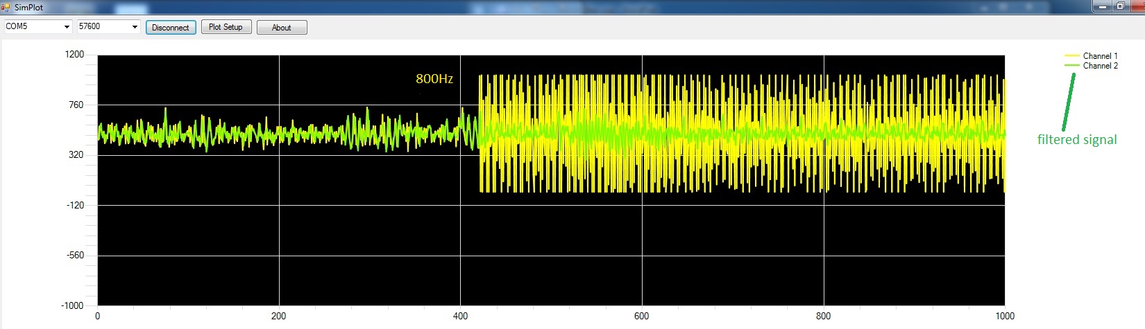
Then I generate two sine-waves with Audacity and recorded them with my Arduino via the microphone: The first sine-wave with 150Hz and the second with 800Hz.
Theoretically the first wave should pass and the second should be blocked. But both were reduced.
See attached pictures. I tried out other filters but without success. Im not sure if the filters didnt work or if I made errors at the sketch or library? If someone would have an idea it would be great.
Sorry for my bad English!
Thanks a lot: scjurgen; doggenj; Brijesh; for your work and publications!
thanks and greets
AdaZus
Hello Magician,
many thanks your fast reply!
I changed the delay to 0.1ms and now it works!
My highest frequency that I want detect is ca. 400Hz. The sample frequency should be the double of the highest frequency, right? Sample frequency of 1000Hz?
But the filters should block also higher frequencies than 400Hz (to 20.000Hz). Do they work anyway?
But the filters should block also higher frequencies than 400Hz (to 20.000Hz). Do they work anyway?
Is it question? Who are they? I don't understand.
BTW, delay() function doesn't take float as an argument, you can't pass 0.1. Other things, you should measure how long does it take to call Filter.run()., it wouldn't be surprise if you don't need delay at all if filter eats up more than a few millisec.
My goal is to process only the frequencies from 0Hz to 400Hz while a band is playing. Im not interested in the upper frequencies produced by the musical instruments. Afterwards I would love to program Bandpass filters to isolate singular notes. For example an “A” with 110Hz. But one step after another. Does it ok for my application to use a sample rate of 1000Hz? I didnt know that delay() function doesn't take float. Also I dont know how to measure the time for calling “Filter.run()” or other orders in generally? I’m a newbie in programming. Do you know perhaps other libraries or sketches with included Bandpassfilter? I found your postings here: http://forum.arduino.cc/index.php/topic,164915 but the web page: http://coolarduino.wordpress.com/2012/06/28/stereo-audio-vu-meter-on-arduino/ sadly doesnt exist anymore.
Hello,
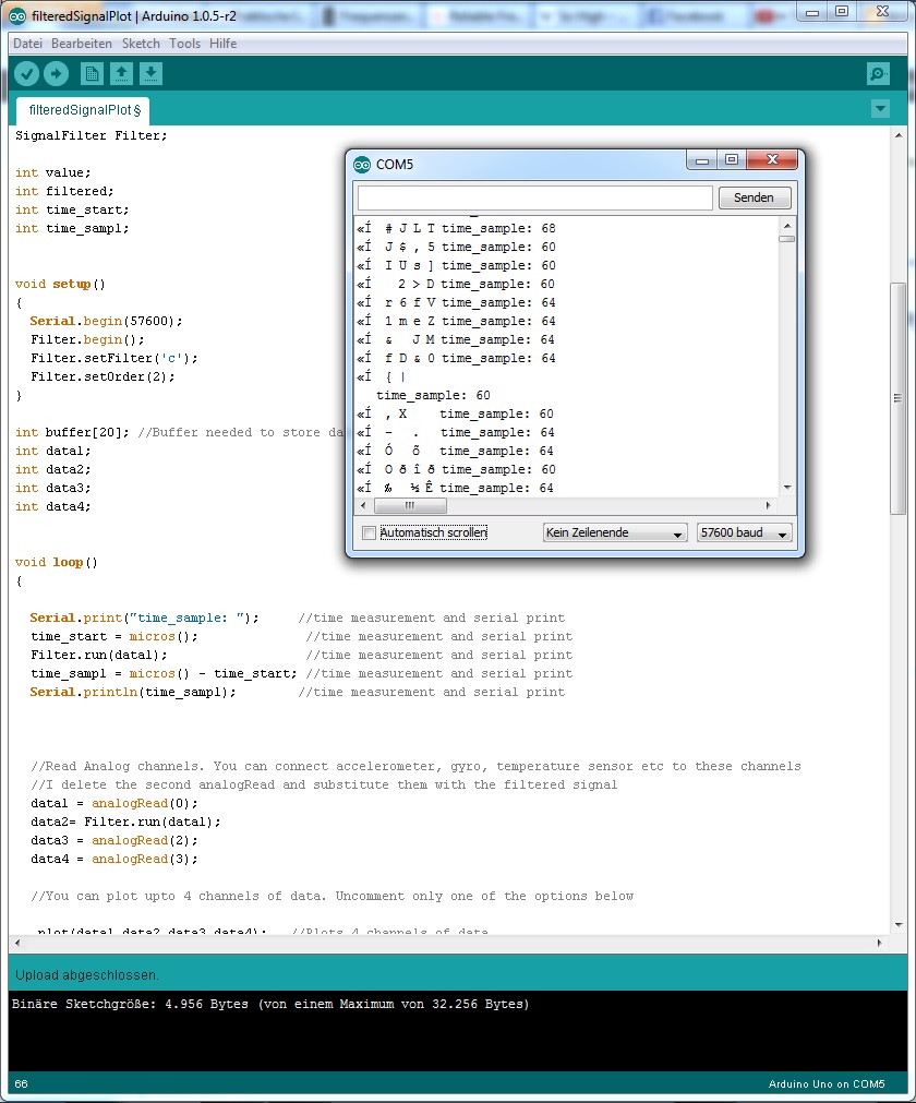
Now I have included the time measurement in my sketch. I hope I made it in the correct way…:
// Arduino Signal Filtering with RealTimePlot


// Arduino Signal Filtering Library
// Copyright 2012-2013 Jeroen Doggen (jeroendoggen@gmail.com)
//http://jeroendoggen.github.io/Arduino-signal-filtering-library/
//http://www.schwietering.com/jayduino/filtuino/


/*
SimPlot Demo

Samples Analog Input and sends them over serial port to be plotted in SimPlot.
This Demo software uses the default serial port "Serial".
Upto to 4 channels of data can be plotted.

For details of SimPlot go to
www.negtronics.com/simplot
http://www.negtronics.com/simplot/simplot-code-samples/plot-analog-input-data
 */


#include <SignalFilter.h>

SignalFilter Filter;

int value;
int filtered;
int time_start;
int time_sampl;


void setup()
{
  Serial.begin(57600);
  Filter.begin();
  Filter.setFilter('c');
  Filter.setOrder(2);
}

int buffer[20]; //Buffer needed to store data packet for transmission
int data1;
int data2;
int data3;
int data4;


void loop()
{

  Serial.print("time_sample: ");     //time measurement and serial print
  time_start = micros();              //time measurement and serial print
  Filter.run(data1);                  //time measurement and serial print
  time_sampl = micros() - time_start; //time measurement and serial print
  Serial.println(time_sampl);        //time measurement and serial print


  //Read Analog channels. You can connect accelerometer, gyro, temperature sensor etc to these channels
  //I delete the second analogRead and substitute them with the filtered signal
  data1 = analogRead(0);
  data2= Filter.run(data1);
  data3 = analogRead(2);
  data4 = analogRead(3);

  //You can plot upto 4 channels of data. Uncomment only one of the options below

   plot(data1,data2,data3,data4);   //Plots 4 channels of data
//  plot(data1,data2,data3);      //Plots 3 channels of data
 // plot(data1,data2);            //Plots 2 channels of data
  // plot(data1);                  //Plots 1 channel of data

  //delay(1); //Read and plot analog inputs every 1ms.
}

//Function that takes 4 integer values and generates a packet to be sent to SimPlot.
void plot(int data1, int data2, int data3, int data4)
{
  int pktSize;

  buffer[0] = 0xCDAB;             //SimPlot packet header. Indicates start of data packet
  buffer[1] = 4*sizeof(int);      //Size of data in bytes. Does not include the header and size fields
  buffer[2] = data1;
  buffer[3] = data2;
  buffer[4] = data3;
  buffer[5] = data4;

  pktSize = 2 + 2 + (4*sizeof(int)); //Header bytes + size field bytes + data

  //IMPORTANT: Change to serial port that is connected to PC
  Serial.write((uint8_t * )buffer, pktSize);
}

//Function that takes 3 integer values and generates a packet to be sent to SimPlot.
void plot(int data1, int data2, int data3)
{
  int pktSize;

  buffer[0] = 0xCDAB;             //SimPlot packet header. Indicates start of data packet
  buffer[1] = 3*sizeof(int);      //Size of data in bytes. Does not include the header and size fields
  buffer[2] = data1;
  buffer[3] = data2;
  buffer[4] = data3;

  pktSize = 2 + 2 + (3*sizeof(int)); //Header bytes + size field bytes + data

  //IMPORTANT: Change to serial port that is connected to PC
  Serial.write((uint8_t * )buffer, pktSize);
}

//Function that takes 2 integer values and generates a packet to be sent to SimPlot.
void plot(int data1, int data2)
{
  int pktSize;

  buffer[0] = 0xCDAB;             //SimPlot packet header. Indicates start of data packet
  buffer[1] = 2*sizeof(int);      //Size of data in bytes. Does not include the header and size fields
  buffer[2] = data1;
  buffer[3] = data2;

  pktSize = 2 + 2 + (2*sizeof(int)); //Header bytes + size field bytes + data

  //IMPORTANT: Change to serial port that is connected to PC
  Serial.write((uint8_t * )buffer, pktSize);
}

//Function that takes 1 integer value and generates a packet to be sent to SimPlot.
void plot(int data1)
{
  int pktSize;

  buffer[0] = 0xCDAB;             //SimPlot packet header. Indicates start of data packet
  buffer[1] = 1*sizeof(int);      //Size of data in bytes. Does not include the header and size fields
  buffer[2] = data1;

  pktSize = 2 + 2 + (1*sizeof(int)); //Header bytes + size field bytes + data

  //IMPORTANT: Change to serial port that is connected to PC
  Serial.write((uint8_t * )buffer, pktSize);
}
So the time sample I measured is ca. 62us. See attachment. What do you think about?
Furthermore I tested the filter again whit a sweep from 0 to 1000Hz.The filter doesn`t work in the right way! The filtered signal is blocked (low amplitude) already at ca. 160Hz, but should be blocked only at 300Hz (filter design Lower Corner= 300Hz). At ca. 390 the amplitude of the filtered signal increase and stay up until 700Hz.Than the filtered signal remain low until 870Hz. From 870Hz until 1000Hz the amplitude of the filtered signal is again at a high level.
Number of microseconds since the program started (unsigned long)
Than, you have also call to the plot() inside the loop, why you don't measure a time?
Third, serial print is slow, change your sketch in a way, that you keep timing measurements results in global variables, for example time_filter, time_plot etc, and print results ONLY by request. Here is just an idea, not working code for you:
void loop()
{
//  Serial.print("time_sample: ");     //time measurement and serial print
  time_start = micros();              //time measurement and serial print
  Filter.run(data1);                  //time measurement and serial print
  time_filter = micros() - time_start; //time measurement and serial print
 // Serial.println(time_sampl);        //time measurement and serial print

  time_start = micros();              //time measurement and serial print
  data1 = analogRead(0);
  data2= Filter.run(data1);
  data3 = analogRead(2);
  data4 = analogRead(3);
  time_sampl = micros() - time_start; //time measurement and serial print

 time_start = micros();              //time measurement and serial print
    plot(data1,data2,data3,data4);   //Plots 4 channels of data
 time_plot = micros() - time_start; //time measurement and serial print

  //CONSOLE COMMAND LINE INTERFACE
  if (Serial.available() > 0) {
    incomingByte = Serial.read();
    if (incomingByte == 'm') {             // FREE MEMORY BYTES
      Serial.println(freeRam());
    }
    if (incomingByte == 'x') {
      for (int i = 0; i < FFT_SIZE; i++){
        Serial.print("\t");
        Serial.print( xin[i], DEC );
        if ((i+1)%16 == 0) Serial.print("\n");
      }
      Serial.print("\n");
    }
  }

}
And last, doing measurements of sampling, you should discover that analogRead takes ~120 usec each, about 500 usec by 4 reads, so if loop contains sampling and nothing else inside, your maximum sampling rate is 2 kHz
Hello, yes I visited the page. I toke the example as reference. Firstly I used unsigned long but then I changed to int. Newbie error!
I have to read out only one analog input (one microphone). (Now I commented it out in my sketch). So the theoretically maximum sampling rate is 8.333Hz (1.000.000us/120us). Many thanks for your example! I need some time to understand. Than hopefully we will see how much time it needs to call the filters.
 // Arduino Signal Filtering an time measurement for Analog Read and Filter


// Arduino Signal Filtering Library
// Copyright 2012-2013 Jeroen Doggen (jeroendoggen@gmail.com)
//http://jeroendoggen.github.io/Arduino-signal-filtering-library/
//http://www.schwietering.com/jayduino/filtuino/


/*
SimPlot Demo

Samples Analog Input and sends them over serial port to be plotted in SimPlot.
This Demo software uses the default serial port "Serial".
Upto to 4 channels of data can be plotted.

For details of SimPlot go to
www.negtronics.com/simplot
http://www.negtronics.com/simplot/simplot-code-samples/plot-analog-input-data
 */


#include <SignalFilter.h>

SignalFilter Filter;


unsigned long time_start;
unsigned long time_sampl;
unsigned long time_plot;

int buffer[20]; //Buffer needed to store data packet for transmission
int data1;
int data2;
//int data3;
//int data4;

int incomingByte = 0;


void setup()
{
  Serial.begin(57600);
  Filter.begin();
  Filter.setFilter('c');
  Filter.setOrder(2);
}


void loop()
{


   time_start = micros();              //time measurement
   data1 = analogRead(0);              //for analog 0
   data2 = Filter.run(data1);          // for filter calculation
   time_sampl = micros() - time_start; //time measurement


  // time_start = micros();              //time measurement
  // plot(data1,data2);                   //Plots 2 channels of data
 //  time_plot = micros() - time_start; //time measurement


  //Read Analog channels. You can connect accelerometer, gyro, temperature sensor etc to these channels
  //I delete the second analogRead and substitute them with the filtered signal
  data1 = analogRead(0);
  data2= Filter.run(data1);
  // data3 = analogRead(2);
 // data4 = analogRead(3);

  //You can plot upto 4 channels of data. Uncomment only one of the options below

//   plot(data1,data2,data3,data4);   //Plots 4 channels of data
 // plot(data1,data2,data3);      //Plots 3 channels of data
// plot(data1,data2);            //Plots 2 channels of data
  // plot(data1);                  //Plots 1 channel of data

  //delay(1); //Read and plot analog inputs every 1ms.


  if (Serial.available() > 0) {
    incomingByte = Serial.read();
    if (incomingByte == 'm') {             // press m and read time in microsec for Filter.run(data1)
      Serial.println(time_sampl, DEC);
        }
      }
   /*
    if (Serial.available() > 0) {
    incomingByte = Serial.read();
    if (incomingByte == 'n') {             // press n and read time in microsec for plot(data1,data2)
      Serial.println(time_plot, DEC);
        }
      }*/

}


 /*
//Function that takes 4 integer values and generates a packet to be sent to SimPlot.
void plot(int data1, int data2, int data3, int data4)
{
  int pktSize;

  buffer[0] = 0xCDAB;             //SimPlot packet header. Indicates start of data packet
  buffer[1] = 4*sizeof(int);      //Size of data in bytes. Does not include the header and size fields
  buffer[2] = data1;
  buffer[3] = data2;
  buffer[4] = data3;
  buffer[5] = data4;

  pktSize = 2 + 2 + (4*sizeof(int)); //Header bytes + size field bytes + data

  //IMPORTANT: Change to serial port that is connected to PC
  Serial.write((uint8_t * )buffer, pktSize);
}

//Function that takes 3 integer values and generates a packet to be sent to SimPlot.
void plot(int data1, int data2, int data3)
{
  int pktSize;

  buffer[0] = 0xCDAB;             //SimPlot packet header. Indicates start of data packet
  buffer[1] = 3*sizeof(int);      //Size of data in bytes. Does not include the header and size fields
  buffer[2] = data1;
  buffer[3] = data2;
  buffer[4] = data3;

  pktSize = 2 + 2 + (3*sizeof(int)); //Header bytes + size field bytes + data

  //IMPORTANT: Change to serial port that is connected to PC
  Serial.write((uint8_t * )buffer, pktSize);
}  */
/*
//Function that takes 2 integer values and generates a packet to be sent to SimPlot.
void plot(int data1, int data2)

 {
  int pktSize;

  buffer[0] = 0xCDAB;             //SimPlot packet header. Indicates start of data packet
  buffer[1] = 2*sizeof(int);      //Size of data in bytes. Does not include the header and size fields
  buffer[2] = data1;
  buffer[3] = data2;

  pktSize = 2 + 2 + (2*sizeof(int)); //Header bytes + size field bytes + data

  //IMPORTANT: Change to serial port that is connected to PC
  Serial.write((uint8_t * )buffer, pktSize);
}   */


 /*
//Function that takes 1 integer value and generates a packet to be sent to SimPlot.
void plot(int data1)
{
  int pktSize;

  buffer[0] = 0xCDAB;             //SimPlot packet header. Indicates start of data packet
  buffer[1] = 1*sizeof(int);      //Size of data in bytes. Does not include the header and size fields
  buffer[2] = data1;

  pktSize = 2 + 2 + (1*sizeof(int)); //Header bytes + size field bytes + data

  //IMPORTANT: Change to serial port that is connected to PC
  Serial.write((uint8_t * )buffer, pktSize);
}   */
I hope I didnt make big errors! Explanation: Only when I enter and send “m” (in serial monitor window) I get time measurement for “AnalogIn0” and “Filter.run(data1);”. It gives me 172usec (attachment: Time_mes_plotoff). So theoretically I have a sample rate of 5.814Hz. I tried also to measure the time for „plot(data1,data2)“, but its unreadable, because of all other symbols in the serial monitor window, read from real time plotting orders (attachment: Time_mes_ploton).
The thing is that I used the real-time-plot only to check if the filter works accurately. Maybe the right description of the problem I have now is the Heisenbug. Wikipedia: “Heisenbugs occur because common attempts to debug a program, such as inserting output statements or running it in a debugger, usually modify the code, change the memory addresses of variables and the timing of its execution.”
In my end project I wouldn`t need the real-time-plot anymore. I want only that a LED switches on when a tone with a certain threshold (amplitude) passes the bandpassfilter. Maybe does it be also a good way to check if the filter library works fine? So with my lowpassfilter (cutoff frequency 300Hz) the LED should be shine until 300Hz and switched off with all frequencies above 300Hz.
Or do you know other, maybe more accurate methods to test the filters?
Or do you know other, maybe more accurate methods to test the filters?
I'd create a big array, 256 or 512 values to store results of the filtering. Like in your initial setup, you feed a sinewave, arduino filterring data and store them to an array. You printing results by request whenever you change input, or like to observe a process.
As you can see, slow float math replaced by integer approximation.
You says:
Then I opened “SignalFilter.cpp” and substitute the Chebyshev Filter of 2nd Order with my new Filter code:
Code:
if(_order==2) {
_v[0] = _v[1];
_v[1] = _v[2];
_v[2] = (4.153748378268e-1 * data)
Hello,
now I wrote a sketch like described in my previous posts.
Switch a LED on if amplitude from filtered signal reaches an arbitrary level:
// Arduino Signal Filtering and LED on if filter amplitude reaches an arbitrary threshold.
// 2014

// Arduino Signal Filtering Library
// Copyright 2012-2013 Jeroen Doggen (jeroendoggen@gmail.com)
//http://jeroendoggen.github.io/Arduino-signal-filtering-library/
//http://www.schwietering.com/jayduino/filtuino/


#include <SignalFilter.h>  // Filter Library
SignalFilter Filter;

//const int analogPin = A0;    // pin that the sensor is attached to
const int ledPin = 13;         // pin that the LED is attached to
const int threshold = 1000;    // an arbitrary threshold level that's in the range of the analog input


unsigned long time_start;    // variable for time measurement start
unsigned long time_sampl;    // variable for time measurement sample


unsigned int data1;
unsigned int data2;

int incomingByte = 0;


void setup()
{

  pinMode(ledPin, OUTPUT);     // initialize the LED pin as an output:
  Serial.begin(9600);
  Filter.begin();
  Filter.setFilter('c');       // filter settings: c=Cebycheff  b= Bessel
  Filter.setOrder(2);          // filter settings: order 1 or 2

}
/*
      Filter characteristics are stored in: “SignalFilter.cpp”.
      Current filter settings and code: for “c” “2”

  /// runChebyshev: Low Pass; 2nt Order; cutoff =300Hz; sampling=5000Hz; long type 8bit;
  “-1bit saturation” enabled;
                        _v[0] = _v[1];
			_v[1] = _v[2];
			long tmp = ((((data * 3009876L) >>  6)	//= (   2.2425325955e-2 * x)
				+ ((_v[0] * -3295982L) >> 1)	//+( -0.7858234574*v[0])
				+ (_v[1] * 3557026L)	//+(  1.6961221536*v[1])
				)+1048576) >> 21; // round and downshift fixed point /2097152

			_v[2]= (short)tmp;
			return (short)((
				 (_v[0] + _v[2])
				+2 * _v[1])); // 2^
*/


void loop()
{

  //Read Analog Input... you can connect accelerometer, gyro, temperature sensor, microphone etc to the channel

 // int data1 = analogRead(analogPin);
  data1 = analogRead(0);       //Read Analog channels
  data2 = Filter.run(data1);   //Read the filtered signal


  time_start = micros();               //time measurement
   data1 = analogRead(0);              // for Analog Pin A0
   data2 = Filter.run(data1);          // for filter calculation
   time_sampl = micros() - time_start; //time measurement math


  if (Serial.available() > 0) {
    incomingByte = Serial.read();
    if (incomingByte == 'm') {         // enter and sent "m" in serial monitor window and read time in microsec for Filter.run(data1) and analog read
    Serial.print("Time Sample = ");
    Serial.println(time_sampl, DEC);
        }
      }

/*
http://arduino.cc/en/Tutorial/IfStatement
the variable called analogValue is used to store the data collected from a Analog Pin A0.
This data is then compared to a threshold value.
If the analog value is found to be above the set threshold the LED connected to digital pin 13 is turned on.
If analogValue is found to be < threshold, the LED remains off. */

      // read the value of the microphone:
      // int analogValue = analogRead(analogPin);

  // if the filter value is high enough, turn on the LED:
  if (data2 > threshold) {
    digitalWrite(ledPin, HIGH);
  }
  else {
    digitalWrite(ledPin,LOW);
  }

   // print the analog value:
   // Serial.print("In: ");
   // Serial.print(data1);
   // Serial.print(" - Out: ");
   // Serial.println(data2);
   // delay(500);        // delay in between reads for stability


}
To check if the sketch works, firstly I did some test directly on A0. I set threshold level to 1000 and it works fine: If I speak in the microphone the LED turns on, if not the LED remains dark.
Then I made tests with the filtered signal. Insert data2 instead of data1 at code:
if (data2 > threshold) {
digitalWrite(ledPin, HIGH);…..
but now the LED switches on and off randomly!
I think the filter gives out incorrect numbers. But before Im goning to check this I have another question: Are the input signals correctly for filter computation? Because the microphone gives out a value off ca. 512 (1024/2) if its quite, and when it's loud a signal of 1024 or 0. In the microphone circuit is implemented a DC offset. So the microphone waves doesn't oscillate around 0V but around 2,5V. See also:
Are the input signals correctly for filter computation?
Good question, you should subtract DC offset. Other things, declare data1 and data2 as signed. And you don't need time measurements anymore, otherwise you are reading input twice.
// int data1 = analogRead(analogPin);    <-- int, not unsigned int !
  data1 = analogRead(0) -512;       //Read Analog channels
  data2 = Filter.run(data1);   //Read the filtered signal
Hello Magician, thank you very much for the support! Now it works!
I tested it with a sweep from 0-1000Hz. LED on until ca. 400Hz (threshold= 512). LED off, for all frequencies above. I set cut off at 300Hz, the LED switches off only at 400Hz. I think this can have to do with the filter curve and the characteristics which defines them… Chebyshev or Bessel; order...
Here the code:
// Arduino Signal Filtering Test
// Turn a LED on if filter amplitude reaches an arbitrary threshold.
// 2014

// Arduino Signal Filtering Library
// Copyright 2012-2013 Jeroen Doggen (jeroendoggen@gmail.com)
//http://jeroendoggen.github.io/Arduino-signal-filtering-library/
//http://www.schwietering.com/jayduino/filtuino/


#include <SignalFilter.h>  // Filter Library
SignalFilter Filter;

const int ledPin = 13;        // pin that the LED is attached to
const int threshold = 512;    // an arbitrary threshold level that's in the range of the analog input

/* Variable for time measurement
unsigned long time_start;    // variable for time measurement start
unsigned long time_sampl;    // variable for time measurement sample
int incomingByte = 0;        // sets incoming Byte to 0
*/

int data1;     // variable for Analog In
int data2;     // variable for filter


void setup()
{
  pinMode(ledPin, OUTPUT);     // initialize the LED pin as an output:
 // Serial.begin(9600);        // used only printing (debugging)
  Filter.begin();
  Filter.setFilter('c');       // filter settings: c=Cebycheff  b= Bessel
  Filter.setOrder(2);          // filter settings: order 1 or 2
}

/*
      Filter characteristics are stored in: “SignalFilter.cpp”.
      Current filter settings and code: for “c” “2”

  /// runChebyshev: Low Pass; 2nt Order; cutoff =300Hz; sampling=5000Hz; long type 8bit;
  “-1bit saturation” enabled;
                        _v[0] = _v[1];
			_v[1] = _v[2];
			long tmp = ((((data * 3009876L) >>  6)	//= (   2.2425325955e-2 * x)
				+ ((_v[0] * -3295982L) >> 1)	//+( -0.7858234574*v[0])
				+ (_v[1] * 3557026L)	//+(  1.6961221536*v[1])
				)+1048576) >> 21; // round and downshift fixed point /2097152

			_v[2]= (short)tmp;
			return (short)((
				 (_v[0] + _v[2])
				+2 * _v[1])); // 2^
*/


void loop()
{
 // Read Analog Input... you can connect accelerometer, gyro, temperature sensor, microphone etc to the channel

  data1 = analogRead(0)-512;      //Read Analog channel (value of microphone) and substract DC-Offset from Microphone "BOB-09964"
  data2 = Filter.run(data1);      //Read the filtered signal

/*
http://arduino.cc/en/Tutorial/IfStatement
the variable called data1 is used to store the data collected from a Analog Pin A0.
This data is then compared to a threshold value.
If the the value is found to be above the set threshold the LED connected to digital pin 13 is turned on.
If analogValue is found to be < threshold, the LED remains off. */


  // if the filter value is high enough, turn on the LED:
  if (data2 > threshold) {
    digitalWrite(ledPin, HIGH);
  }
  else {
    digitalWrite(ledPin,LOW);
  }

   /* time measurement for debugging:

   time_start = micros();               //time measurement
   data1 = analogRead(0);              // for Analog Pin A0
   data2 = Filter.run(data1);          // for filter calculation
   time_sampl = micros() - time_start; //time measurement math

  if (Serial.available() > 0) {
    incomingByte = Serial.read();
    if (incomingByte == 'm') {         // enter and sent "m" in serial monitor window and read time in microsec for Filter.run(data1) and analog read
    Serial.print("Time Sample = ");
    Serial.println(time_sampl, DEC);
        }
      } */
}
If you see further errors or if you have improvement suggestions please write me.
Now I’m going to implement a BandPassFilter. Let’s see if I can make it!
but they are maybe to heavy for the microcontroller (slow sample rate). I did some tests and the filter didn’t work anymore.
What do you think, it’s principally possible to use a filter and generate sine-waves simultaneously?
I found also this Audio Shield:
Maybe that’s a good solution because it works “asynchronously as an interrupt, so the Arduino can perform tasks while the audio is playing.”
What do you think about? Do you know maybe other methods to generate sine-waves which don’t overload the microcontroller?