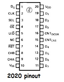
I would really appreciate some help to get an Avago HCTL-2022 chip working so I can accurately read a 1000p/r optical encoder. I have considered faster boards and such but I think a dedicated IC is best as pulses could get very fast with such a high resolution encoder on a fast stepper motor. Some boards have hardware quadrature encoders included in their architecture but the threads regarding setting those up seem much more complicated.
I have read the datasheet: https://media.digikey.com/pdf/Data%20Sheets/Avago%20PDFs/HCTL-2032,2022.pdf
And read a forum post: help with avago 2022 for quadrature shield - #20 by ickyan - Project Guidance - Arduino Forum ,
and have implemented some code that was claimed to work and I am using an Arduino Mega (clone):
/*
~~~~~~~~~~~~~~~~~~~~~~~~~~~~~~~~~~~~~~~~~~~~~~
Reading decoder HCTL-2022 to count pulses from
an encoder using Arduino Mega 2560
Written by Hanna Hellman, 2016-07-08
~~~~~~~~~~~~~~~~~~~~~~~~~~~~~~~~~~~~~~~~~~~~~~

Arduino Pin       HCTL-2022 function
------------------------------------
DIG 9             /RST (active low)
DIG 11            SEL1
DIG 12            SEL2
DIG 13            /OE (active low)
DIG 22->29        Data pins D0->D7
+5V               VDD
GND               VSS
from encoder      CHA
from encoder      CHB
not connected     INDEX
not connected     U/D
not connected     TEST
External clock    CLK
*/

// Global variable declaration
volatile long countData = 0; // 32-bit int (signed?) the count represents absolute position


void setup() {
  Serial.begin(9600);

  pinMode(9, OUTPUT);
  digitalWrite(9, LOW); // /RST resets the internal counter between runs
  delay(10);
  digitalWrite(9, HIGH); // Stay high for rest of the run

  // Set all pins in PORTA (digital pins 22->29 on the Mega) as input pins
  for(int i = 22; i<30; i++) {
    pinMode(i, INPUT);
  }
  // Set pins 5,6,7 in PORT B (digital pins 11,12,13 on the Mega) as output pins
  for(int j = 11; j<14; j++) {
    pinMode(j, OUTPUT);
    digitalWrite(j, LOW);

  }

}
/*-------------------------------------------------
  -------------------Functions---------------------
  -------------------------------------------------*/
byte getMSB(){
/*Get stable data for the most significant byte of countData*/

  byte MSBold = PINA;       // read datapins D0->D7 and store in MSBold
  byte MSBnew = PINA;       // read again immediatly after to assure stable data
  if (MSBnew == MSBold){
    byte MSBresult = MSBnew;
    return MSBresult;
  }
  else getMSB();
}

byte getSecond(){
/*Get stable data for the 2nd byte of countData*/
  byte secondOld = PINA;       // read datapins D0->D7 and store in secondOld
  byte secondNew = PINA;       // read again immediatly after to assure stable data
  if (secondNew == secondOld){
    byte secondResult = secondNew;
    return secondResult;
  }
  else getSecond();
}

byte getThird(){
/*Get stable data for the 3rd byte of countData*/
  byte thirdOld = PINA;       // read datapins D0->D7 and store in thirdOld
  byte thirdNew = PINA;       // read again immediatly after to assure stable data
  if (thirdNew == thirdOld){
    byte thirdResult = thirdNew;
    return thirdResult;
  }
  else getThird();
}

byte getLSB(){
/*Get stable data for the least significant byte of countData*/
  byte LSBold = PINA;       // read datapins D0->D7 and store in LSBold
  byte LSBnew = PINA;       // read again immediatly after to assure stable data
  if (LSBnew == LSBold){
    byte LSBresult = LSBnew;
    return LSBresult;
  }
  else getLSB();
}

long mergeFunc(byte MSBresult, byte secondResult, byte thirdResult, byte LSBresult){
/*Merges the 4 bytes returning one 32-bit variable called countData*/
  long tempVar = 0;
  tempVar |= ((long) MSBresult << 24) | ((long) secondResult << 16) | ((long) thirdResult << 8) | ((long) LSBresult << 0);
  countData = tempVar;
  return countData;
}


void loop() {

  digitalWrite(13, HIGH); // Set OE to HIGH (disable)
  delay(25);  // need a better way

  digitalWrite(11, LOW);
  digitalWrite(12, HIGH); // SEL1 = 0 and SEL2 = 1

  digitalWrite(13, LOW); // Set OE to LOW (enable)
  byte MSBresult = getMSB();


  digitalWrite(11, HIGH);
  digitalWrite(12, HIGH); // SEL1 = 1 and SEL2 = 1
  byte secondResult = getSecond();

  digitalWrite(11, LOW);
  digitalWrite(12, LOW); // SEL1 = 0 and SEL2 = 0
  byte thirdResult = getThird();

  digitalWrite(11, HIGH);
  digitalWrite(12, LOW); // SEL1 = 1 and SEL2 = 0
  byte LSBresult = getLSB();

  digitalWrite(13, HIGH); // Set OE to HIGH (disable)
  delay(25);

  countData = mergeFunc(MSBresult, secondResult, thirdResult, LSBresult);
  Serial.println("Counter: ");
  Serial.println(countData);
  Serial.println("\n");


  }

  /*
  Algorithm:

  disable OE (high)
  wait 25 ms
  set sel1= 0 and sel2 = 1 to read MSB
  enable OE (low)

  getMSB()
  set sel1 =1 and sel2=1
  get2nd()
  set sel1 = 0 and sel2 = 0
  get3rd()
  set sel1 = 1 and sel2 = 0
  getLSB()

  disable OE (high)
  wait 25 ms
  */
I have hooked up the 'external clock' using an Arduino Nano running the below code which is claimed to produce a 1MHz clock signal.
//Use Timer/Counter1 to generate a 1MHz square wave on Arduino pin 9.
//J.Christensen 27Apr2012

//**********from https://forum.arduino.cc/index.php?topic=103370.0


void setup(void)
{
    DDRB = _BV(DDB1);                  //set OC1A/PB1 as output (Arduino pin D9, DIP pin 15)
    TCCR1A = _BV(COM1A0);              //toggle OC1A on compare match
    OCR1A = 7;                         //top value for counter
    TCCR1B = _BV(WGM12) | _BV(CS10);   //CTC mode, prescaler clock/1
}

void loop(void)
{
}
Now I am only getting an output of 0 regardless of turning the encoder or not. If the problem is in the coding it could be something to do with parsing the binary data which seems to be a concern in this post:
https://forum.arduino.cc/index.php?topic=521849.0
If the problem is in the circuit, perhaps I have not wired correctly of maybe some of the unused pins need to be grounded? Do I need any pull downs or pull ups?
Perhaps the Arduino Nano producing the clock signal is not working, could the jumpers and breadboard be attenuating or interfering with the 1MHz pulse?
Can anyone help me to debug this?
I have attached a schematic for my circuitry, and a photo of the breadboard.
I would be extremely helpful if someone can help me interface this chip or suggest how to debug this?
It is for a prototype I am making on a tight budget that will show an invention I have for zero emissions transport (currently I have not earned a penny from this). Final application if for position control of linear motion.
If no one can help and I can't figure out how to debug it, are there many other options? Builtin quadrature decoders on the Due or Teensy 3.x seem much more complicated to set up that this IC, and I could waste too much time. My last resort might be getting a very fast dev. board and using a software method of reading the encoder using interrupts and hoping that it is fast enough (it worked with Arduino Nano but was way to slow and missed many counts when not turned smooth and slow, not something a stepper will be doing).
Anyway thanks for looking,
Yan
edit May-11-18
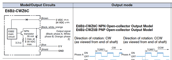
Now working! Original code seems to have no problems after initial testing with a fixed circuit. The problem was not tieing the open-collector encoder outputs high . Working circuit shown in later post on May-11-18


