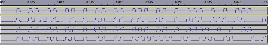
It does not seem to be manchester encoded, from my limited understanding. The first capture on the screenshot was taken when the device read 46.2F (7.9C) and 46% humidity. The second capture was 21.0F (-6.1C) and 17% humidity.
The first part of the sequence seems to be the same in all the captures I've taken, which I'm assuming is a unique device code...
Any help would be appreciated. I'm still a bit confused on how to read these things.
I guess I'm just confused on how to read the graphic above... It may be inverted, but I'm not sure. I found this page that was helpful: http://alyer.frihost.net/thn128decoding.htm
But I'm not sure if I'm even interpreting my 1's and 0's correctly...
If I take the short segments as a 1 and the long segments as a 0, I get:
Since there are never two long gaps in a row, its probably not a bit in itself - the code is probably a short pulse for one symbol and a short pulse followed by a gap for the other bit. If we call these 0 and 1 that gives:
MarkT:
Since there are never two long gaps in a row, its probably not a bit in itself - the code is probably a short pulse for one symbol and a short pulse followed by a gap for the other bit. If we call these 0 and 1 that gives:
Which makes the messages the same length, which is encouraging.
The 101010110101 sequence at the start is probably packet-synchronization preamble.
More data points needed to progress further perhaps?
Whoa, thanks Mark... that makes a ton of sense. I've taken several other samples and they all begin with the same sequence, so I'd agree with you that the 101010110101 sequence seems to be a preamble or perhaps some sort of device ID.
The unit transmits several bursts of the same bit sequence, perhaps 12 or 13 times per sample I've taken - it leaves a longer gap in between each repetition. Because there's so few bits in the sequence maybe that's its means of a CRC check... just say it until it gets right
I've attached a couple more samples where the display read 86.0F and 16% (top in attachment) and 85.1F and 16% (bottom in attachment). All the samples I've taken begin with 101010110101. With the long gap at the end, do you think the last bit would be a 1?
If I understand them correctly, they come out to be:
Typically radio packet preambles are alternating 1's and 0's to enable accurate clock-recovery and decrease the risk of confusing noise for a packet.
The actual values in the packet may be raw ADC outputs from the sensors, which might be odd units - hence the need for loads of examples to tease-out the meaning.
Repeating the packet with different spacing is to enable it to get past various forms of repetitive or bursty interference with high likelyhood (I presume the system does not use a packet-acknowledgement protocol as transceivers at each end add to cost).
The actual values might even be encoded of course... Perhaps 1 should be 0 and 0 should be 1? bit order could be LSB first or MSB first - have fun code-breaking!
Yeah, have considered LSB first, perhaps they are raw ADC outputs... The bit stream just does not seem to be long enough to contain both humidity and temperature in a BCD mode. How would I go about decoding raw ADC outputs?
I've taken about 10 samples so far of various temps and humidities and they all begin with the same bit sequence 101010110101.
Another interesting thing the manual said is that the base station can use up to 3 separate sensors, and to wait at least an hour between adding new sensors to the system on initial setup. Makes me wonder about device codes in the bit stream.
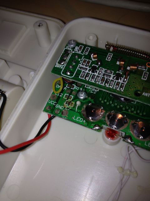
I wonder if it would be helpful to take the transmitter apart and see what's going on inside.
Alright, I'm officially stumped. Everything I've found on google related to other weather station protocols have many more bits than the signal that my thermo/hygro sensor gives me.
At the beginning of every message, no matter what the temperature or the humidity reads, I have the common bits 101010110101, which as I mentioned earlier I'm guessing is probably some sort of device ID. But that only leaves 13 or 14 bits left in the stream to store a sign bit, temperature (with 1 decimal point), and humidity value.
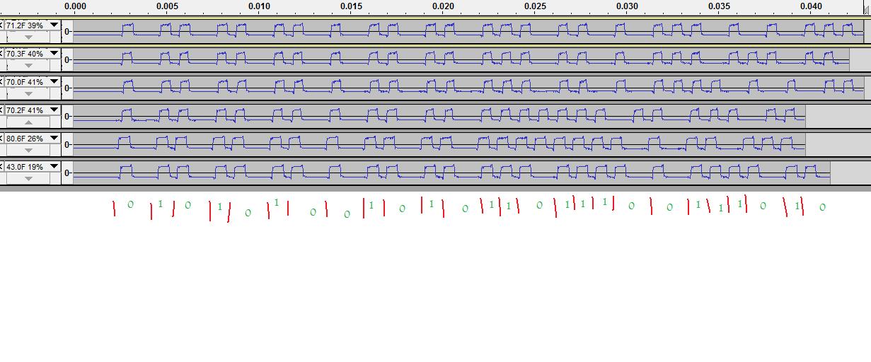
For instance, the value I just captured, 71.2F and 39% humidity was: 101010110101 00101100111001
Here are a couple more, closer together:
70.2F 41%
10101011010100000010100101
70.0F 41%
10101011010100101100011101
That seems to rule out BCD mode, which would require at least 4 bits per digit, if there were 4 temperature digits and 2 humidity digits.
Are there any other types of common encoding systems that I should look into? Maybe this bitstream is somehow compressed, but I really have no idea how that would work. Any sort of pointers in the right direction, even if they are just a hunch, would be helpful!
I think we really need several more examples of the transmitter output to have any chance of decoding the signal.
I know you say the transmitter repeats the data several times but how often does the transmitter send new data?
Would it be possible to attach examples of the entire multi-burst sequence as raw WAV or upload to file sharing site that we may download them.
I've attached several raw wav files of a bit stream with values fairly close together to be able to hopefully find the difference between them. I can give more broad ranged values too if you'd like.
Sample B: transmitter read 71.2F and 39% humidity
Sample C: transmitter read 70.3F/21.3C and 40% humidity
Sample E: transmitter read 70.0F/21.1C and 41% humidity
Sample F: transmitter read 70.2F/21.2C and 41% humidity
The transmitter sends the burst of new data approximately every 75 seconds.
Thanks for any insights whatsoever, no matter how small!
Thanks for the samples. They are quite low level but with a bit of amplification I get the idea. Looking at them stacked on top of each other (see picture) and I wonder if it is maybe not Manchester encoded. It looks more like a MFM encode but that's normally used for magnetic media use.
Can you open the transmitter case without damage and maybe see what components are inside?
Edit:
Forgot to ask if you could supply more samples over larger ranges please.
Just to let you know what my thinkings are sofar. As transmission length varies depending on content and no long highs I feel sure it's not Manchester encoding. I wonder if it's far simpler than that in that a 1 is a single peak and a 0 is a peak followed by a trough (see image for better idea). The bit values could be reversed (peak for 0 & peak/trough for 1).
I had a quick look at the online manual and it says humidity ranges from 20% to 99% in 1% increments (though one of the samples you sent said 19% humidity?) so the range is 79 (99-20) that can fit in 7 bits. Temperature range is stated as -20 to +70 in 0.1 increments that fit's in 10 bits if you multiply by 10 to remove decimal point.
I also wonder if the last 2 bits are stop bits
A couple of samples of minus C temperatures would be helpful please.
Yes, we were talking about the possibility of that encoding scheme in a few of the earlier posts on this thread. It's still interesting to me though because with that scheme, all of the samples I have taken begin with the same bit sequence 101010110101. Perhaps a preamble/device id/"channel number" of some sort...
But that does not leave many bits left to represent temperature and humidity. Despite the manual, I have seen humidities much less than 20% before, reported on the interior and exterior display. I've attached a quick photo as proof (showing a 16% value).
I've got the transmitter in the freezer now so I will be able to give you some very cold samples very shortly.
One thing to consider: if the values sent back are raw data from the two sensors then there is no guarantee that they will have the same bit-order. Also I suspect the encoder chip used will be a standard part for IR remote controls - this link at ladyada seems worth reading: http://www.ladyada.net/learn/sensors/ir.html
Wow, you're on to something. I never considered the transmitter sending different sensor data each burst, but that makes a lot of sense. Here are some consecutive samples that I took earlier:
It looks like Reading 2, Reading 4, and Reading 6 all seem to work out with your formula (after converting to C)! I wonder what reading 1, 3 and 7 mean... Perhaps "no change" or some sort of ack/ping packet?
I'll go see what happens with bits 8 and 9 with negative C temps.
I can only assume that as 0.0C = 12 then the unit only reads to -12.0C and not the -20.0C as stated in the manual. It also seems the minimum humidity is 16% and not 20% as stated in the manual. The interesting one is as below that I can only assume to be battery level of transmitter. 101010110101 0001xxxxxxxxss
EDIT:
***IGNORE THIS The complete breakdown as I see it.
101010110101    Preamble
00              ?Possible device ID (when more than one transmitter used)
xx              Control bits to define Data bits meaning. 00=Humidity, 01=?Battery, 10=Temperature
xxxxxxxx        Data bits. For humidity it's the correct value.
                For temperature divide by 10 and add 12 to get Centegrade value.
                For ?Battery unknown.
01              Postamble
101010110101    Preamble
0               ?Unknown. Possible extra data bit OR device ID (when more than one transmitter used)
xxxxxxxxxxx     Data bits.
                If number <=100 then it's humidity.
                If number >=300 then subtract 500 and divide by 10 to get Centegrade temperature,
01              Postamble