I intend to build a severino board as my first project with arduino. The board needs a 10µF non-polarized electrolytic capacitor that seems to be difficult to find where I live (couldn't find it on ebay as well, but maybe i didn't search with the right keywords ?)
I guess the quick and dirty solution would be to put a polarized cap but this just sounds like a "fail" to me
I read that a non-polarized cap is just two polarized caps connected in series opposition. If i get it right i just need to modify a little bit the pcb to hold 2 capacitors.
Do you know what value i should choose for the 2 capacitors ? (two 10µF caps ?)
Of course, every other idea to solve this problem is welcome.
In this situation (Two electrolytic capacitors "back to back" ), I believe that this is not really a "2 Capacitors in Series" situation because one capacitor or the other is a low impedance when reverse biased. So in the past I have used two capacitors of the "Same as the nominal" value. Worked for the 2 or 3 times I did this in the past 25 years So 10uF for your case...
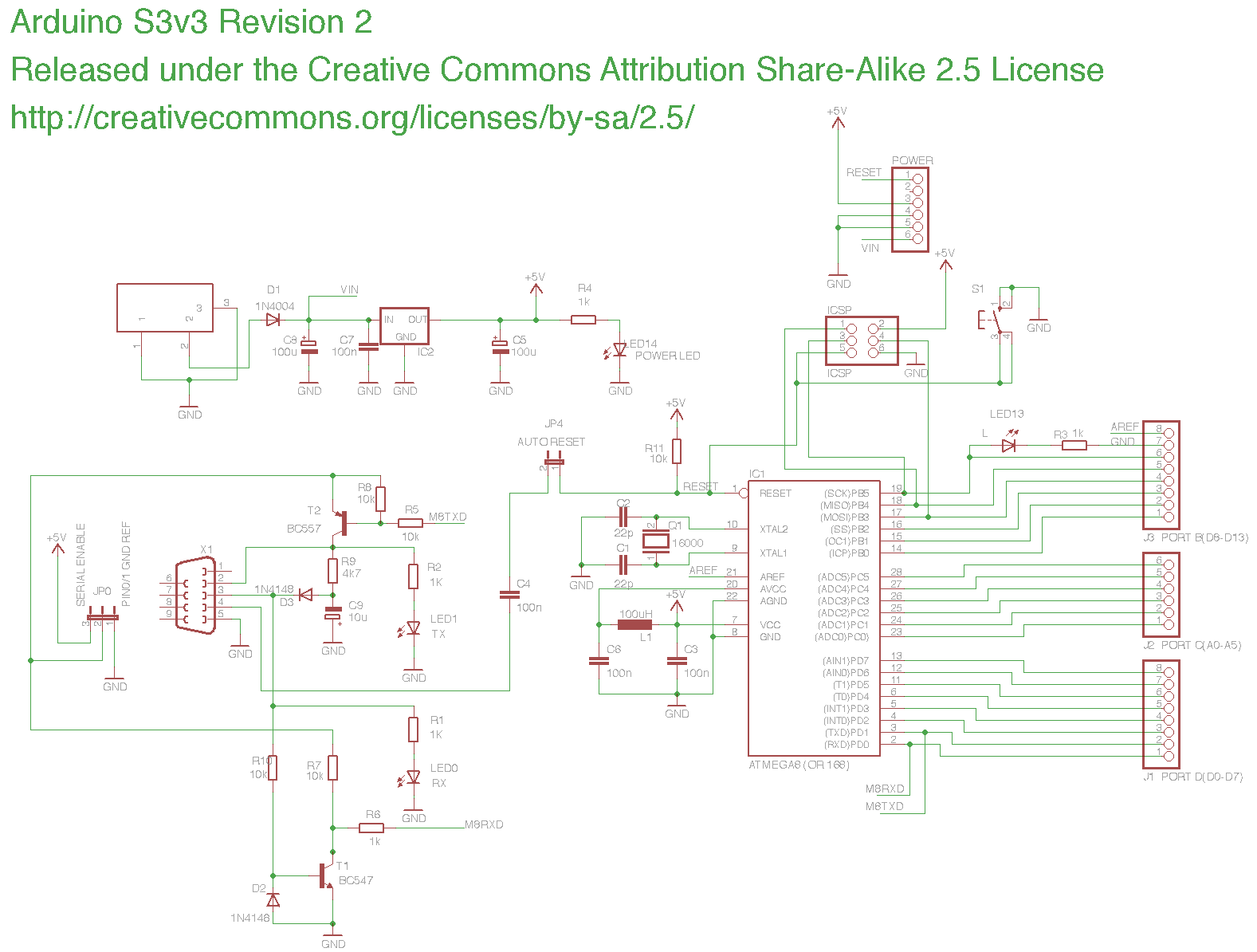
I only see 1 10uF (C9) and it looks polarised to me (+ to ground though, but it's an odd bit of circuitry there)
there are some 100nF, but that's easy!
This has an RS-232 Serial input/output! So those signals swing both + and - (or they need to to be compatible with most all serial ports on whatever computer.)
So: Where does any negative voltage come from, anyway??
When the RS-232 Receive Data (DB-9 pin 3) is "Marking" ie not sending (and during the Mark pulses on normal data), D3 charges up C9 to a negative voltage (Whatever the connected computer's RS-232 driver puts out)..
Mmmmm...
When the Arduino is Transmitting to the attached computer, T2 swings RS-232 Transmit Data (DB-9 Pin 2) from +5 (through JP0) to the negative voltage that C9 is charged to. Keeping the RS-232 Gods happy.
Ummm..
Received data also drives T1 who translates the RS-232 voltage swings to TTL (+5 to Ground) and it's base-emitter diode D2 clamps the negative swing.
BUT -- (An Official Engineering Event that needs to be considered)
IF wiring or something is messed up, or the Computer sends a RS-232 BREAK,
THEN C9 COULD go to opposite polarity. SO it would be safer if it was a non-polarized type.
I might have taken a different approach and put a diode pointing down across C9 to protect against that BUT. Easier to find than a non-polarized capacitor.
Hmmmm..
Other Opinions???
PS: Your "Just use a polarized capacitor" "Probably works, most of the time"..
The original Serial Arduino used a polarized capacitor in a particular orientation. It apparently worked fine.
When I designed my alternate PCB, I noticed that the cap was backward, because (I said), it was charged to **-**Vrs232 from the rs232 connector to provide the negative voltage for the rs232 conversion. So I put the cap in the other way, and my board worked too.
When (?) did the S3V3 single sided PCB, he said "WestfW is right, but the cap can also charge to +5V through the transistor when the rs232 cable is not plugged in, so the cap needs to be bipolar." This seems to be the "most correct" evaluation.
But it seems that it's not very critical. Perhaps the voltages involved are low enough compared to the typical cap voltages that normal caps act relatively bipolar anyway. I don't know. If you can't find a bipolar cap, just stick a normal 10uF cap in there any-which-way and see if it works. If it doesn't work, reverse the cap and try again. If it still doesn't work, THEN you can go looking for bipolar caps (although probably the problem is elsewhere.)
westfw:
The original Serial Arduino used a polarized capacitor in a particular orientation. It apparently worked fine.
...
If you can't find a bipolar cap, just stick a normal 10uF cap in there any-which-way and see if it works. .
[/quote]
No, that's not a good idea. It is KNOWN that normal operation puts a negative voltage on the "top, on the diagram" end of the cap.
The + terminal of a typical polarized cap should always go to ground in this case.
[quote author=Terry King link=topic=52354.msg373916#msg373916 date=1297832492]The diode would need to be in parallel with the cap, "pointing down". In series would not allow current to flow OUT for Q2 to swing negative.
yes, but then the capacitor would discharge directly through the diode (?), that would be worse
The best solution is indeed use a simple polarized cap. It's not so bad since I have a dozen of them.
[/quote]
No, the diode "pointing down" will not discharge the cap if the cap is charged in the normal situation in which it's "top" end is NEGATIVE. It will only conduct if something tries to drive the voltage at the top of the Cap POSITIVE. So in normal operation the diode has no effect. I think it's the easiest solution: diodes are very easy to find; non-polarized caps are more difficult.
But you're in the best position to prove or disprove all this!
Please run both the non-polarized cap AND the polarized cap + diode, and tell us your results.
Ok i was confused with the reverse charge. The idea definitely is worth the try (don't expect to get the result tomorrow as the pcb isn't etched and I plan to add some other things in the schematics).
Do I need to add a current limiting resistor with the diode or everything is fine like that ?
yeah, there's no problem with the capacitor. I was thinking about the fact that the diode is only used when the serial cable is unplugged, so the current flows from T2 to ground. There is already a 4k7 resistor that will limit current but I didn't know if it was enough.
