Hi all. First off, an introduction. I'm John Huebbe... new to electronics but experienced with programming. Just picked up an Arduino and some components a week ago. So far, so good with simple projects (LEDs, speaker, push buttons, small 7 segment display).
I'm building a large (2 to 5 inch high numbers) 6 digit 7 segment display. Some background info... I already have my code working while using the embedded-lab SPI7SEGDISP8.56 MAX7219 based serial 8-digit seven segment LED display module Soldering the SPI7SEGDISP8.56 serial 8-digit seven segment LED display kit | Embedded Lab (took me longer to solder up than program)
From reading a ton of forum posts (most where CrossRoads has replied) it looks like it would be best not to use the MAX7219 to drive larger displays and I think it best to use the TPIC6B595 to drive them. Right?
So, I'm trying to come up with a basic schematic using the ExpressSCH software, but I don't see a TPIC6B595 component. I already tried searching but couldn't find a component to download. Does anyone already have this made? Or, have I missed seeing it in the software?
Also, does anyone already have a schematic drawn up using these?
TPIC6B595 is good for driving higher voltage displays, where 10-12V is needed to drive 3-4-5 LEDs/segment.
With ExpressSCH is dirt simple to make your own component.
Highlight an existing component, use the menu commands to ungroup it, revise as needed, then select all to regroup and save as a custom component.
I can send you my TPIC6B595 symbol when I get home. Send me a PM after 5:00PM east coast time as a reminder.
I've posted schematics showing that part as well. Are you multiplexing the digits, or just using 1/digit?
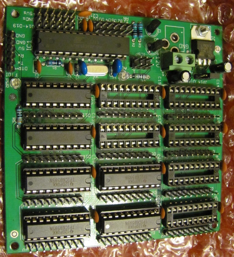
This board I offer ($6 for bare board) can drive up to 12 digits seperately. I'm also using it in another project to multiplex 56 digits (altho less brightly due to the multiplexing). http://www.crossroadsfencing.com/BobuinoRev17/
I haven't really decided on a specific 7 segment display yet, but most of the larger displays I see are 7-12 volt. I'm not really set on a certain type or size just yet.
But maybe eBay isn't the best choice? I don't see many specs on that display (like brightness). I want a bright display for outdoor viewing in the sun.
I've seen some other displays on Digikey
6.8V 10mA
or
Mouser
8V 30mA
I've also seen some that are only 1.85V 30mA (although not in stock)
So far, I've been working on a small prototype on my breadboard. Once I get the software to work how I want it, then I'll start making a full size version. I've been trying to read a lot and see what others have done before, but lots of projects look to be unique. Just trying to figure out all of the different options out there for what will work best for me. Daunting task for a non-electronics guy.
I'll PM you later for the component for expressPCB software. Thanks!
(I'm still amazed at how easy it is to program something on the Arduino and have it do things. Never thought it would be this easy.)
Or make your own digits, chunks of LED strip lights for each segment.
The digikey/mouser parts are faint, only 10s of mCD. You need much more for outdoor use:
These will show up nice!
Yes, Arduino pretty easy to use. Programming seems like fancy BASIC to me. But then again, I've been exposed to a lot of different software over the years. Biggest challenge to the coding was keeping the ; and { } straight when I started with Arduino. Gets easier the more you do it.
Only reservations would be soldering up all of those LEDs onto boards for 6 digits. Plus, I'd have to make a custom board (unless you know of boards available for purchase)
Thru hole, you're only looking at 21 LEDs/digit, won't take long.
I made my own here by soldering the LEDs to 80x100mm Velleman perfboard, and then wire wrapping them in parallel to be driven from 5V source.
Didn't take long at all.
I used the really bright LEDs (these came from superbrightleds.com in different colors) and limited them to a few mA, because 20mA was waaay too bright indoors! Needed sunglasses for testing!
Wow, looks cool. Making my own LED segments might be an option I'll consider. I just initially figured it would be easier to buy the segments so I would have less assembly work.
As for your LED driver board (using TPIC6B595), is this what you mean ?
I'm starting to consider the power requirements of my project... and to have a bright display for outdoor use, it seems like I'll need a big battery.
So, using the TPIC6B595, is there a way to control the brightness of the LEDs, in order to reduce my power requirements when it isn't full sun (cloudy days, night, indoors)?
If I make my own digits out of LEDs; assuming 28 LEDs for 6 small segment, 77 LEDs for 2 large segments, 10 LEDs for 3 round lights; I get 352 LEDs (I might reconsider how many I use for the large ones). If I run them at 20mA, I'll have about 7000mA for the display. Seems like a lot of power, since I was considering batteries that have a capacity of 7Ah. Would only run my display for 1 hour, right?
So... if there is an easy way I could have a dial or menu system control the brightness, I would prolong the display time.
I have my TPIC6B595 registers wired up to some small 7 segment displays. I have tested them with a sketch that I downloaded from Nick Gammon's site Gammon Forum : Electronics : Microprocessors : Using a 74HC595 output shift register as a port-expander and all of the segments light up, so I know everything is wired up correctly and working. Hard to see, but I have a capacitor across the + and - for a decoupling capacitor. I also just used 1 resistor per display, since I didn't have 42 resistors for each led segment, so it does dim as more segments light up.
Now, my question. Are there some code samples/examples on how to display numbers onto my 6 digit display? Previously when I was using the Embedded Lab SPI 7-seg display http://embedded-lab.com/blog/?p=6862 the code was very simple. Like:
#include <LedControl.h> //  need the library
LedControl lc=LedControl(4,3,5,1); // lc is our object Pin 4, 3, 5  and 1 display

clockminute = minute();
clockhour = hour();
lc.setDigit(0,6,clockhour,false);
lc.setDigit(0,3,clockminute,false);
Where I used lc.setDigit to send the display what number I wanted for my hour, minute, second.
Is there a similar Library for using 595 shift registers? Also, should I be using SPI.h or ShiftOut() to update my display? (I've started reading a bit about each)
I use SPI.transfer() for shift registers. Way faster.
Assuming your 6 are daisy chained:
digitalWrite(ssPin LOW);
SPI.transfer(fontArray[byte0]);
SPI.transfer(fontArray[byte1]);  // send out the font information that represents the data for byte1
SPI.transfer(fontArray[byte2]);
SPI.transfer(fontArray[byte3]);
SPI.transfer(fontArray[byte4]);
SPI.transfer(fontArray[byte5]);
digitalWrite(ssPin, HIGH);

with
byte fontArray [] = {
// B-DP-g-f-e-d-c-b-a
B00111111, // 0          a
B00000110, // 1      f        b
B01011011, // 2          g
//etc.                    e        c
B01011111, // 9           d       DP, or one of the indicator lights
};

and the bytes might even come from an array:
SPI.transfer(fontArray[dataArray[x]]);  // double look up! send out the font information from dataArray position x

so this might be in a loop:
for (x=0; x<6; x=x+1){
SPI.transfer(fontArray[dataArray[x]]);
}

You could use MAX7219 to drive the 6 smaller displays from 5V, using its brightness register to control the brightness level.
On the TPIC6B595, use PWM on the output enable pin to control brightness level.

MAX7219:
digitalWrite(ssPin, LOW);
SPI.transfer(register1address);
SPI.transfer(register1data);
digitalWrite(ssPin, HIGH);
// really need to bury that in a library?  I don't think so
Is there a standard way they should be hooked up? Like, should the first display be on the far left or far right?
Here is what I show with my display and how it's hooked up.
Serial In goes to #1, then Serial out of 1 goes to in of #2, etc...
Using your suggestions, here is my test code. Works so far.
// Test sketch using 6 TPIC6B595 shift registers
#include <SPI.h>

const static byte charTable[128] = {
  // B-DP-g-f-e-d-c-b-a
  //    a
  //f       b
  //    g
  //e       c
  //    d       DP

  //0         1         2         3         4         5         6         7
    B00111111,B00000110,B01011011,B01001111,B01100110,B01101101,B01111101,B00000111,
  //8         9
    B01111111,B01100111
};

const byte LATCH = 10;     //Arduino Latch Pin = 10
const byte NumberOfSR = 6; //Number of Shift Registers

byte DisplayData [NumberOfSR]; //Array for numbers that go in the 6 digit display

void refreshDisplay ()
{
  digitalWrite (LATCH, LOW);
  for (byte i = 0; i < NumberOfSR; i++)
    SPI.transfer (DisplayData [i]);
  digitalWrite (LATCH, HIGH);
}

void clockDisplay ()
{
  DisplayData [0] = charTable[1];
  DisplayData [1] = charTable[2];
  DisplayData [2] = charTable[3];
  DisplayData [3] = charTable[4];
  DisplayData [4] = charTable[5];
  DisplayData [5] = charTable[6];
  refreshDisplay ();
}

void setup ()
{
  SPI.begin ();
}

void loop ()
{
    clockDisplay ();
}
I'll most likely use the decimal points for my lights and just use 2 more TPIC6B595's for the other 2 larger digits. Or, I may even use another 595 for the lights. That way I can daisy chain everything with some headers & cables.
CrossRoads:
The way its coded, it will display 654321.
Its up you to define what goes where, there isn' a standard.
Ok, that's what I thought.
CrossRoads:
You have no current limit resistors? That will burn out your LEDs eventually. The TPIC6B595 can sink a lot of current.
I have 1 small resistor on each of the common anodes of the 7 segment displays. I sized it so if I was displaying the number 1, it would be about 10mA. If I show an 8, the display dims more. I would add resistors to each individual led for my final project, but I didn't want to put in 42 resistors on my breadboard for this. (plus I didn't have that many on hand)
Ok, so I'm starting to get together a list of components for my full size prototype, and I'm thinking about power requirements.
Can anyone help me or point me in the right direction with batteries?
For instance, I'm looking at 2 LiPo batteries. One is 5500mAh at 7.5V and the other is 5500mAh at 15.0V. I plan on using a DC-DC switching regulator to step down the battery voltage to 5V for the Arduino (like this: http://www.digikey.com/product-detail/en/OKI-78SR-5%2F1.5-W36-C/811-2196-5-ND/2259781?cur=USD) and use the voltage straight from the battery to power the LED displays. (good / bad idea?)
For the sake of simplicity, lets say each of my display segments uses 6 LEDs and each LED is 2.5V. So, for my 7.5V battery I could wire 2 rows of 3 LEDs in series and for my 15V battery I could wire 6 LEDs in series (correct?)
Now with my battery, will my displays last just as long, since each battery is 5500mAh?
If you wanted 6 LED segments, you would need 2 segments of 3 series-wired LEDs driven in parallel, consuming 40mA from a 7.5V source,
or, 1 segment of 6 series wired LEDs consuming 20mA from a 15V source.
You could use a TPIC6B595 to sink the 20mA or 40mA from the segments.
If you had 3 pairs of 2-LED strings then you would consume 60mA/segment.
Take advantage of the higher voltage & decreased current by running more LEDs in series.
Convert enough 5V current to power the '328P and the shift registers if you go that route.
Ok, I think I understand. As for the battery, I'll probably go 15V w/switching regulator.
Some more updates. I have my breadboard now hooked up to my GPS and it is pulling in the GPS time and displaying it on the 6 digit displays. I also have a 4 line 20 character LCD screen. It is hooked up to the Arduino via a Software Serial connection. I have both the 6 digit LED displays and the 4 line LCD displaying the time from GPS.
Now, my problem. The LCD lags behind the 6 digits. It is around a half second delay.
Is this because there is a long delay with using Serial? Or could it be the cheap screen I'm using?
From the LCD datasheet, it looks like I can change the BAUD rate with a command. The default is 9600. The display can go all the way to 115.2K. I'll try changing it tonight and see if I get better results.
Also, the LCD display can be controlled by either Serial, I2C, or SPI. Is one better over the other?