Could please help me. I am using the Arduino UNO and a Maxim MAX9611, the communication is i2C with the Wire.h I am confused where to start. I understand I2c but need getting communication correct between UNO & MAX9611. How to I start talking to the MAX9611 and reading the information? The datasheet is at the following website http://datasheets.maximintegrated.com/en/ds/MAX9611-MAX9612.pdf
I do understand i2c, but my difficulty is the structure talking to the MAX9611
Have you tried anything? What is "my difficulty" exactly?
I would expect at this stage to see a bit of code where you initialize I2C, try to communicate with the device at the documented address, try to read a register, that sort of thing.
I have tried. Following is my program: (My result is "Temp is 31.14" on the LCD, which is incorrect and does not track the temperature)
#include <TimerOne.h>
/*
 Analog pins 4 (SDA),5(SCL)
 */
#include <Wire.h>
#include <Adafruit_MCP23017.h>
#include <Adafruit_RGBLCDShield.h>
// The LCD and DS3132 use the I2C SCL on analog pin 5 and SDA on analog pin 4.
Adafruit_RGBLCDShield lcd = Adafruit_RGBLCDShield();

int temp_MSB;
int temp_LSB;
double tempresolution = 0.48;

void setup()
{
  lcd.begin(16, 2);
  Serial.begin(9600);
  Wire.begin();
}

void loop()
{
  int i, sign, temp1;		//added sign and temp1. JZ 05/21/2012
  double temperature;
  lcd.setCursor(0,1);
  while (1) {
    Wire.write(0xE0);
    Wire.write (0x08);
    Wire.requestFrom(0xE1, 1);
    temp_MSB = Wire.read();

    Wire.write(0xE0);
    Wire.write (0x09);
    Wire.requestFrom(0xE1, 1);
    temp_LSB = Wire.read();

    // changed for MAX9611 internal temperature output (9 bits with sign). JZ 05/21/2012
    sign = (temp_MSB>>8 & 0x1);		//extract sign bit
    temp1 = (((temp_MSB<<1) & 0xFE)|((temp_LSB>>8)&0x1));	//extract internal temperature ADC steps
    if(sign)
    {
      temperature = (-1)*((~temp1 & 0xFF) + 1)*tempresolution;	//sign bit=1, temperature is negative (two's compliment)
    }
    else
    {
      temperature = temp1 * tempresolution;		//otherwise, the temperature is a positive number
    }
    temperature = ((temperature * 1.8) + 32); 	//convert to degree F

  lcd.setCursor(0,1);
  lcd.print("Temp is ");
  if (sign==0)
  {
    lcd.print("-");
  }
  lcd.print(temperature);
  }

}
Oh, right! You have code. It was a secret, though.
Read this before posting a programming question
Please edit your post, select the code, and put it between [code] ... [/code] tags.
You can do that by hitting the # button above the posting area.
You would have got a much faster response if you had read the sticky, and posted your code, in the first place. A day has been gone because you didn't.
My apologies, I made a mistake. Can someone help?
  while (1) {
    Wire.write(0xE0);
    Wire.write (0x08);
    Wire.requestFrom(0xE1, 1);
    temp_MSB = Wire.read();

    Wire.write(0xE0);
    Wire.write (0x09);
    Wire.requestFrom(0xE1, 1);
    temp_LSB = Wire.read();
I do understand i2c, ...
OK, now go read my page, which you obviously haven't so far:
Things that jump out at me:
- You need Wire.beginTransmission
- You need Wire.endTransmission
- I2C device addresses go up to 119 (x77) but you are using 0xE1
I am reading your I2c instructions. I have changed my program to include:
Wire.beginTransmission(0xE0);
Wire.write(0x08);
Wire.endTransmission(); // This function sets the pointer to the registerLocation from where we want to read the data
Wire.requestFrom(0xE1,1);
temp_MSB = Wire.read();
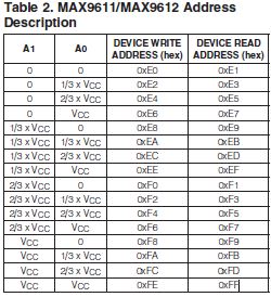
Also the address of the MAX9611 starts at 0xE0 thru 0xEF
combib:
Also the address of the MAX9611 starts at 0xE0 thru 0xEF
The library shifts the address left one and adds in the read/write bit. You want to use 0x70 (half of 0xE0) and leave that part to the library. In other words use 0x70 for both reading and writing.
Run this scanner to prove that point, and to check your wiring is correct:
That worked, and yes something showed up on 70, although it still does not function correctly. I will work on it further and get back to you. Thank you for all your help
Thanks for your help. Following is my code and so far it is working. Next I will add power supply and load.
#include <TimerOne.h>
/*
 Analog pins 4 (SDA),5(SCL)
 */
#include <Wire.h>
#include <Adafruit_MCP23017.h>
#include <Adafruit_RGBLCDShield.h>
// The LCD and DS3132 use the I2C SCL on analog pin 5 and SDA on analog pin 4.
Adafruit_RGBLCDShield lcd = Adafruit_RGBLCDShield();

int temp_MSB;
int temp_LSB;
double tempresolution = 0.50;

void setup()
{
  lcd.begin(16, 2);
  Serial.begin(9600);
  Wire.begin();
}

void loop()
{
  int i, sign, temp1;		//added sign and temp1. JZ 05/21/2012
  double temperature;
  lcd.setCursor(0,1);
  while (1) {
    Wire.beginTransmission(0x70);
    Wire.write(0x08);
    Wire.endTransmission();

    Wire.requestFrom(0x70,2);
    temp_MSB = Wire.read();
    temp_LSB = Wire.read();

    // changed for MAX9611 internal temperature output (9 bits with sign). JZ 05/21/2012
    sign = (temp_MSB>>8 & 0x1);		//extract sign bit
    temp1 = (((temp_MSB<<1) & 0xFE)|((temp_LSB>>8)&0x1));	//extract internal temperature ADC steps
    if(sign)
    {
      temperature = (-1)*((~temp1 & 0xFF) + 1)*tempresolution;	//sign bit=1, temperature is negative (two's compliment)
    }
    else
    {
      temperature = temp1 * tempresolution;		//otherwise, the temperature is a positive number
    }
    temperature = ((temperature * 1.8) + 32); 	//convert to degree F

  lcd.setCursor(0,0);
  lcd.print("Temp is ");
  if (sign==1)
  {
    lcd.print("-");
  }
  lcd.print(temperature);
  }
}
I have written a program (see following) to read the MAX9611 Data and display it on an LCD. I will be changing the program to output to a screen and also have the ability to have up to 16 different addressed MAX9611 ICS reporting. The problem this I have is that the Arduino used a 7 bit i2c address and assumes that the 8th bit is either a one or a zero. In the case of the MAX9611, the write and read addresses are E0/E1, E2/E3, E4/E5, E6/E7, ..... FE/FF. My question is, how do I tell the Arduino that the write/read bit is not necessarily a one or a zero?
/*********************************************************************
 * FileName: 		MAX9611.h
 * Dependencies: 	None
 * Overview:		Defines function prototypes, I2C address, global
 *					variables.
 ********************************************************************/


// ***************** User-configurable parameters ********************


// main voltage range
#define voltage_max 56.3
#define main_voltage_min 1.0

// main current range
#define current_max 10000
#define current_min 0

// I2C address
#define MAX9611_address 0x70 //0x70 is the Arduino MAX9611 address actual address is 0xE0

// Sense resistor values

// *******************************************************************

// Function prototypes

double get_MAX9611_voltage(void);
double get_MAX9611_current(void);

//void init_MAX9611 ();
/*********************************************************************
 * FileName: 		MAX9611.cpp
 * Dependencies: 	MAX9611.h (include here and in main)
 *				Wire.h (include here and in main)
 ********************************************************************/


/*********************************************************************
 * Function:        	void get_MAX9611_voltage (void),
 *				void get_MAX9611_current (void)
 * PreCondition:    	None.
 * Input:           	None.
 * Output:          	None.
 * Side Effects:    	None.
 * Overview:       		Function for obtaining MAX9611 voltage via I2C
 *						bus.
 *
 ********************************************************************/

#include "MAX9611.h"
#include "Wire.h"

double MAX9611_voltage;
double MAX9611_current;

double get_MAX9611_voltage (void){
int msb;
int lsb;


    Wire.beginTransmission(0x70);
    Wire.write(0x0A);
    Wire.write(0x03);
    Wire.endTransmission();

    Wire.beginTransmission(0x70);
    Wire.write(0x02);
    Wire.endTransmission();

    Wire.requestFrom(0x70,2);
    msb = Wire.read();
    lsb = Wire.read();
    Wire.endTransmission();

    MAX9611_voltage = ((msb)<<4)+(lsb>>4);
    MAX9611_voltage = ((MAX9611_voltage/4096)*57.3);

return MAX9611_voltage;
}

double get_MAX9611_current (void){
int msb;
int lsb;
int result;

    Wire.beginTransmission(0x70);
    Wire.write(0x0A);
    Wire.write(0x00);
    Wire.endTransmission();

    Wire.beginTransmission(0x70);
    Wire.write(0x00);
    Wire.endTransmission();

    Wire.requestFrom(0x70,2);
    msb = Wire.read();
    lsb = Wire.read();
    Wire.endTransmission();

    result = ((msb)<<4)+(lsb>>4);
    MAX9611_current = (((result/4096)*440)/.05);

    	return MAX9611_current;
}
#include <MAX9611.h>
#include <Wire.h>
/*
 Analog pins 4 (SDA),5(SCL)
 */
#include <Adafruit_MCP23017.h>
#include <Adafruit_RGBLCDShield.h>
Adafruit_RGBLCDShield lcd = Adafruit_RGBLCDShield();

int msb;
int lsb;

void setup()
{
  lcd.begin(16, 2);
  Serial.begin(9600);
  Wire.begin();
}

void loop()
{
  double volts;
  double current;

  lcd.setCursor(0,1);
  while (1) {


  volts = get_MAX9611_voltage();

  lcd.setCursor(9,0);
  lcd.print(volts, 3);
  lcd.print(" V");

    current = get_MAX9611_current();

  lcd.setCursor(0,0);
  lcd.print(current, 3);
  lcd.print(" A");


  lcd.setCursor(2,1);
  lcd.print((current * volts), 6);
  lcd.print(" Watts");
  }
}
The answer is that the LSB is still a one or zero and the same rules apply for all of the MAX9611 addresses. ![]()