LCD 16x2 + PCF8574T black boxes problem

Hello to everyone,
i'm trying to configure my first LCD display with my Arduino UNO R3.
I bought a 16x2 LCD on the net with a I2C controller board named LCM1602 IIC V1 attached to it with a PCF8574T chip on it
The connection between Aduino and the controller board board are:
+5V to VCC
GND to GND
A4 to SDA
A5 to SCL

I checked the address of the I2C board and it is 0x27
then using the LiquidCrystal_I2C 1.2.1 library and after double and triple checking the connections between the LCD and the controller to know how to configure the display i wrote this simple code

//initialization
LiquidCrystal_I2C lcd(0x27, 2,1,0,9,10,11,12,3,POSITIVE);

//in the setup section
lcd.begin(16,2);
lcd.setCursor(0,0);
lcd.print("Hello, world!");
delay(1000);
lcd.setCursor(0,1);
lcd.print("HI");

but all i can get is the first row full of black boxes on the display and the second totally empty as show in the picture
Anyone can give me a help? this thing is driving me crazy!!

Hi niddu

LiquidCrystal_I2C lcd(0x27, 2,1,0,9,10,11,12,3,POSITIVE);

That seems like a lot of arguments. Try the even simpler example program that comes with the library (edited for your I2C address).

#include <Wire.h> 
#include <LiquidCrystal_I2C.h>

LiquidCrystal_I2C lcd(0x27,16,2);  // set the LCD address to 0x27 for a 16 chars and 2 line display

void setup()
{
  lcd.init();                      // initialize the lcd 
 
  // Print a message to the LCD.
  lcd.backlight();
  lcd.print("Hello, world!");
}

void loop()
{
}

And have you checked the I2C address by using the scanner program?

http://playground.arduino.cc/Main/I2cScanner
Regards

Ray

Or try to initialize it with

LiquidCrystal_I2C lcd(0x27, 2, 1, 0, 4, 5, 6, 7, 3, POSITIVE);

waski:
Or try to initialize it with

LiquidCrystal_I2C lcd(0x27, 2, 1, 0, 4, 5, 6, 7, 3, POSITIVE);

with this initialization is still not working

LiquidCrystal_I2C lcd(0x27,16,2); // set the LCD address to 0x27 for a 16 chars and 2 line display

my library does not support that constructor, i'm using the latest (1.2.1) downloaded from this website
https://bitbucket.org/fmalpartida/new-liquidcrystal/downloads

and i'm sure the address is 0x27 because i got it from the scanner mentioned above

I think the problem is with pin asigning with thi particular LCD backpack. I had the same problem and I had to try many different ones found on internet.

Try

LiquidCrystal_I2C lcd(0x27, 4, 5, 6, 0, 1, 2, 3, 7, POSITIVE);

offcourse you are including wire library in your sketch ? Did you adjuct contrast, using on board potentiometer ?

That's the full code with the last edits but with no clue:

#include <Wire.h>
#include <LiquidCrystal_I2C.h>

LiquidCrystal_I2C lcd(0x27, 4, 5, 6, 0, 1, 2, 3, 7, POSITIVE); 

void setup()
{
  lcd.begin(16,2);
  lcd.backlight();
  lcd.print("Hello, world!");
}

void loop()   
{}

Have you looked here: --> http://arduino-info.wikispaces.com/LCD-Blue-I2C#v1

Don

floresta:
Have you looked here: --> http://arduino-info.wikispaces.com/LCD-Blue-I2C#v1

Don

yep, i also tried this example but always with the same result :frowning:

I've got a question. Is there any way to drive the LCD directly from the arduino connected to the 16 pins without the I2C interface? if yes where can i get some samples?

I've got a question. Is there any way to drive the LCD directly from the arduino connected to the 16 pins without the I2C interface? if yes where can i get some samples?

Absolutely. Start here: --> http://arduino.cc/en/Tutorial/LiquidCrystal

Don

OK, so you have tried the I2Cscanner, but you actually need to use the I2C guesser instead, to tell you the complete descriptor whcih you can then cut and paste into your programs.

Paul__B:
I2C guesser

done and this is the output i got:

Scanning i2c bus for devices..
i2c device found at address 0x27
Device found: PCF8574
<Press <ENTER> or click [Send] to start guessing>
Trying: lcd(0x27, 2, 1, 0, 4, 5, 6, 7, 3, POSITIVE)
<Press <ENTER> or click [Send] to Continue>
Trying: lcd(0x27, 2, 1, 0, 4, 5, 6, 7, 3, NEGATIVE)
<Press <ENTER> or click [Send] to Continue>
Trying: lcd(0x27, 4, 5, 6, 0, 1, 2, 3, 7, NEGATIVE)
<Press <ENTER> or click [Send] to Continue>
Trying: lcd(0x27, 6, 5, 4, 0, 1, 2, 3, 7, NEGATIVE)
<Press <ENTER> or click [Send] to Continue>
Trying: lcd(0x27, 6, 5, 4, 0, 1, 2, 3, 7, POSITIVE)
<Press <ENTER> or click [Send] to Continue>
Trying: lcd(0x27, 4, 5, 6, 0, 1, 2, 3, 7, POSITIVE)
<Press <ENTER> or click [Send] to Continue>
Scanning i2c bus for devices..
Unknown error at address 0x27
No I2C device found
Scanning i2c bus for devices..
Unknown error at address 0x27
No I2C device found
Scanning i2c bus for devices..
Unknown error at address 0x27
No I2C device found

what do you think?

done and this is the output i got:

What did you see on the LCD at each step of the guessing program?

Nothing at all.always black boxes on the first row

I belive your PCF8574 board is a Chinese version which has the wires swapped on the board.This means your wire is not like you think.
Try to use the library I attached below and make sure you remove your library from arduino libraries folder! Don't just comment the folder, remove it to anywhere outside arduino libraries folder.
Unzip this one and past there.
Now open arduino IDE and go to the example and choose LiquidCrystalI2C_Chinese.....
Try to run the hello world now

LiquidCrystal_I2C2004V1_Chinese.zip (19.1 KB)

niddu:
Nothing at all. always black boxes on the first row

Beats me then!

I was curious that the backlight is actually on, that it presumably did so even without any sketch running (plugging the Arduino in with the reset button held) however ...

The message

Scanning i2c bus for devices..
Unknown error at address 0x27
No I2C device found

is concerning also - perhaps bperrybap might deign to kick in on that matter.

So, I went to my cache and got out the backpack in question, already attached to a module. It does indeed start with the backlight on and the descriptor is indeed:

lcd(0x27, 2, 1, 0, 4, 5, 6, 7, 3, POSITIVE)

And inserting that in my favourite "Matrix scanner" sketch works just fine!

HugoPT:
I belive your PCF8574 board is a Chinese version which has the wires swapped on the board.This means your wire is not like you think.

Well, I will grant you one thing, It is a Chinese version!

Something is screwed somewhere.

And to prove we are talking about the same board:

HugoPT:
make sure you remove your library from Arduino libraries folder! Don't just comment the folder, remove it to anywhere outside Arduino libraries folder.

I don't think you need the Chinese library(!), but when you install the fmalpartida library, you did have to move the original library - in its entirety - outside of the Ardunio tree.

Paul__B:

HugoPT:
make sure you remove your library from Arduino libraries folder! Don't just comment the folder, remove it to anywhere outside Arduino libraries folder.

I don't think you need the Chinese library(!), but when you install the fmalpartida library, you did have to move the original library - in its entirety - outside of the Ardunio tree.

niddu,
Stick with fm's library. That library has been thoroughly tested, and is known to work.
There is no need to switch horses at this point.
Make sure you get fm's library directly from his bitbucket site as there are some modified
versions floating around out there.
https://bitbucket.org/fmalpartida/new-liquidcrystal/wiki/Home

The key is to get the constructor correct.
That first constructor you used was really wrong.
There are only 8 output pins numbered 0-7 on the PCF8574 and you were using
pin numbers of 9, 10, 11, and 12. Definitely won't work with that.

The best way is to look at the board traces and see how it is hooked up to the LCD and then put in the
output port pin numbers in the constructor. That is is how it should be done.
It only takes a couple of minutes since these boards are pretty simple.
You might have to use an ohm meter since the backpack is already soldered to the LCD.
After you figure out which LCD pin each of the output port pins (P0 to P7) connects
to , you simply use those numbers in the constructor.

The constructor pin numbers are bit numbers or Px numbers on the PCF8574
and represent the LCD connections as follows:

lcd	LiquidCrystal_IIC( iic_addr, En, Rw, Rs,  d4,  d5,  d6, d7 , bl, bl_polarity);

The guesser sketch tries the all the known combinations of pinouts to try "guess" one that works.
One critical piece of information is what is the backlight doing?
Is it blinking at all? (It should blink 3 times when the constructor guess is correct)
If not, what about if you remove the jumper?

From looking at that photographs, it looks ,like it is wired up as follows:

PCF8574      LCD
P2            en
P1            rw
P0            rs
P4            d4
P5            d5
P6            d6
P7            d7
P3           backlight

(which seems to match Paul's backpack)

What isn't so clear is how the backlight is controlled.
so it is not possible to know the backlight polarity from looking at the photograph.
Are there any components on the back of the backpack?

If there are no components on the back,
it would mean that there are no pullups on the i2c bus.
Pullups on the i2c bus are mandatory. This isn't something you can leave off.
The AVR has its pullups enabled on the bus which often works, but they are way too
weak and well out of spec and sometimes don't work even when using a single device
like this with short wires.
Many people try to use i2c with Arduino without proper pullups, and often get away with it, but
proper pullups are required for reliable operation
and the built in pullups in the AVR are not strong enough.
This may be the cause for the errors that showed up from the guesser.

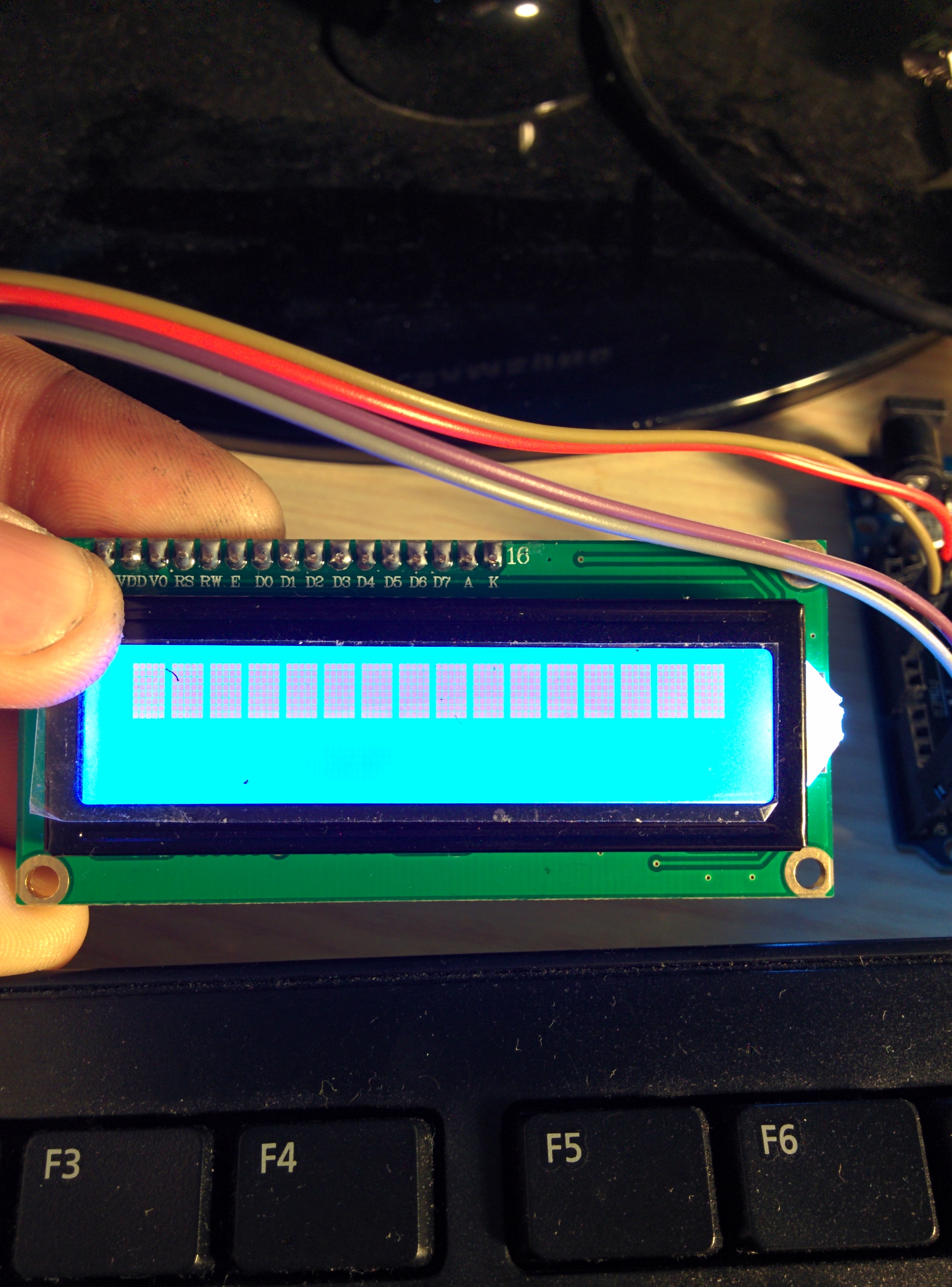
Another question, is while you say the "blocks" is the only thing you get,
are you seeing 1 row or 2 rows of blocks?
If you are seeing more than 1 row of blocks, the contrast pot is mis adjusted.
You should adjust the pot to make sure it is working. At one end the blocks will be full blocks
at the other end no pixels will show up , somewhere in the middle is where you need it to be.

--- bill

so... step by step.
1- i downloaded again the libraries from https://bitbucket.org/fmalpartida/new-liquidcrystal/wiki/Home and placed in the libraries folder in arduino instead of the original ones (moved somewhere else on my pc).

2- followed the traces of my PCF8574 and this is the result for the constructor as agreed with Paul__B
lcd(0x27, 2, 1, 0, 4, 5, 6, 7, 3, POSITIVE)

3-

One critical piece of information is what is the backlight doing?
Is it blinking at all? (It should blink 3 times when the constructor guess is correct)
If not, what about if you remove the jumper?

the backlight is always on with the jumper on and always off when the jumper is off. it never blinks

4-

What isn't so clear is how the backlight is controlled.
so it is not possible to know the backlight polarity from looking at the photograph.
Are there any components on the back of the backpack?

attached you can find a back picture of the backpack

5-

are you seeing 1 row or 2 rows of blocks?

1 row, the top one

Conclusions:
i'm planning to buy a new one... it's getting too wierd for such a simple display

wow...
It looks like there is some damage.
Did you remove the backpack?

That white wire looks like it is on D7.
Was there a wire there before?

I'm a bit stumped. There isn't much that can go wrong
with these simple backpacks, especially if the i2c chip is responding like it is.
The most common issues are:

  • bad solder joints (in the earlier photos, the soldering all looked really good.)
  • incorrect constructor (I think you are using the correct parameters)

What is odd is that the backlight is not blinking.
That solder on the 4.7k resistor (472) looks a bit suspicious on one side.
It looks like a little ball - but maybe it is just the photo.
The circuit looks like it has a 1k pull down and 4.7k series resistor going to the base.
So if the solder didn't flow through that hole on the one side of the 4.7k resistor
all the way to the trace on the other side of the board,
then the PCF8574 won't be able to control the backlight.
My guess is that the jumper when in forces the backlight on, and when out, the
PCF8574 controls it.
(Paul, you could verify this)

Perhaps it needs the pullups to the i2c bus.
They are required and are not present on your backpack.
It could be that i2c lines are not stable enough to work properly/reliably using the internal
AVR pullups so the proper data is not being sent to the chip.

--- bill

Well that wire is my fault while trying to remove the backpack to take the picture but don't worry about it,I fixed it.
So,first of all I will fix the solder on the 4k7 and then what about the pull ups? Which size should they be? They must be connected between SDA and scl and vcc right?