Could you please explain me if I have series or parallel resistors in the image below?
first I believed series because when I cover the LDR I have less tension but it does not make sense because the energy can flow through green cable or through the LDR if the resistance is low (have light).
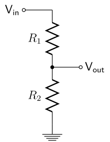
The 10K resistor is in series with the LDR.
The green wire is connected to an analog input which has a resistance of ~100M. (for your experiment this can be considered infinite)
.
The LDR & resistor are in series. Essentially zero current flows through the green wire because the Arduino has very-high input impedance (resistance). The Arduino's analog input can sense the voltage via the green wire, even though no current flows into it.
You've got a [u]Voltage Divider[/u] with one variable resistor. You can measure the voltage divider's output with a multimeter and the multimeter won't have any effect on the voltage at the output, again because the multimeter has "almost infinite" input resistance/impedance. If you put a motor at the voltage divider output (or try to power the Arduino from the voltage divider, etc.), the voltage will drop because the motor is in parallel with the bottom resistor and the voltage divider ratio changes.
When I cover the LDR I notice that the tension at the green cable increases (I mesured with a multimeter) . I imagine that is because left more tension that does not pass through LDR. Am I right ?
"tension" is the wrong word. You mean "voltage" (I hope).
As the light on LDR goes down, the resistance of the LDR increases. This increases the total resistance between across the two resistors, so less current flows (ohm's law) through the two resistors. Since the 10k resistor is still 10k, that means the voltage drop across that resistor is smaller, while the voltage drop across the LDR is larger.
Take a look at Ohm's law - with some basic rearrangement, you can make all the relevant equations. The key thing to remember is that you can assume that no current flows into or out of an arduino pin set as input, so you can set up I = V/R for both resistors - and then they're equal to eachother, so V1/R1 = V2/R2 or V1/V2 = R1/R2, which is of course the basic design equation for a voltage divider.
"High-tension" is normal English usage for very high voltage (50kV+) in electricity
distribution grids, but "tension" is not used for trivial voltages like 11kV or below!
The word voltage can become tension when translated to English. I'm sure the op means voltage
And I know people who call it tension. They call high tension lines or high voltage line take you pick.
But the op used tension for voltage.
What the OP is seeing is the voltage divider changing center voltage because he covered the LDR which makes it read higher where as with light on it the reading will be lower.
Now if the OP wants the reading to go high in light and low in dark just swap the LDR and resistor around.
I've worked with 8400 that's all the tension I need :o But the worst shock I ever got was phone lines 90 volt DC why I didn't think it could shock me I don't know. But never agin.
LarryD:
The 10K resistor is in series with the LDR.
The green wire is connected to an analog input which has a resistance of ~100M. (for your experiment this can be considered infinite)
.
Even tho I could not view the original image from the OP, I assume they are using an analog input.
Even tho you can assume a digital input has 100M ohms impedence, you can't assume that for an analog input pin. Analog input pins use a capacitor, sample and hold, which is designed for about 10k input impedance. A small capacitor (0.1uf) on the analog pin, to ground may be a help.
They bump up the voltage it was a main trunk of 10,000 pairs and the old terminal blocks not puch down like they use now the plant has 5,000 phone lines in it. I was turning on the office and their bank phones and you don't have much room I rub a block that the cover was off I thought it had killed me LOL..
")