I built my "uno" following the tutorial @ http://www.instructables.com/id/DIY-Arduino-or-The-DIY-Duino/
I have been trying to upload a sketch to it but keep getting avrdude: stk500_getsync(): not in sync: resp=0x30.
I have checked for shorts and haven't found any. I have it wired up like found @ Use the FTDI Basic Breakout Board to program an Atmega328P-PU With Optiboot. | Modsbyus.com
My chip does have optiboot bootloader installed.
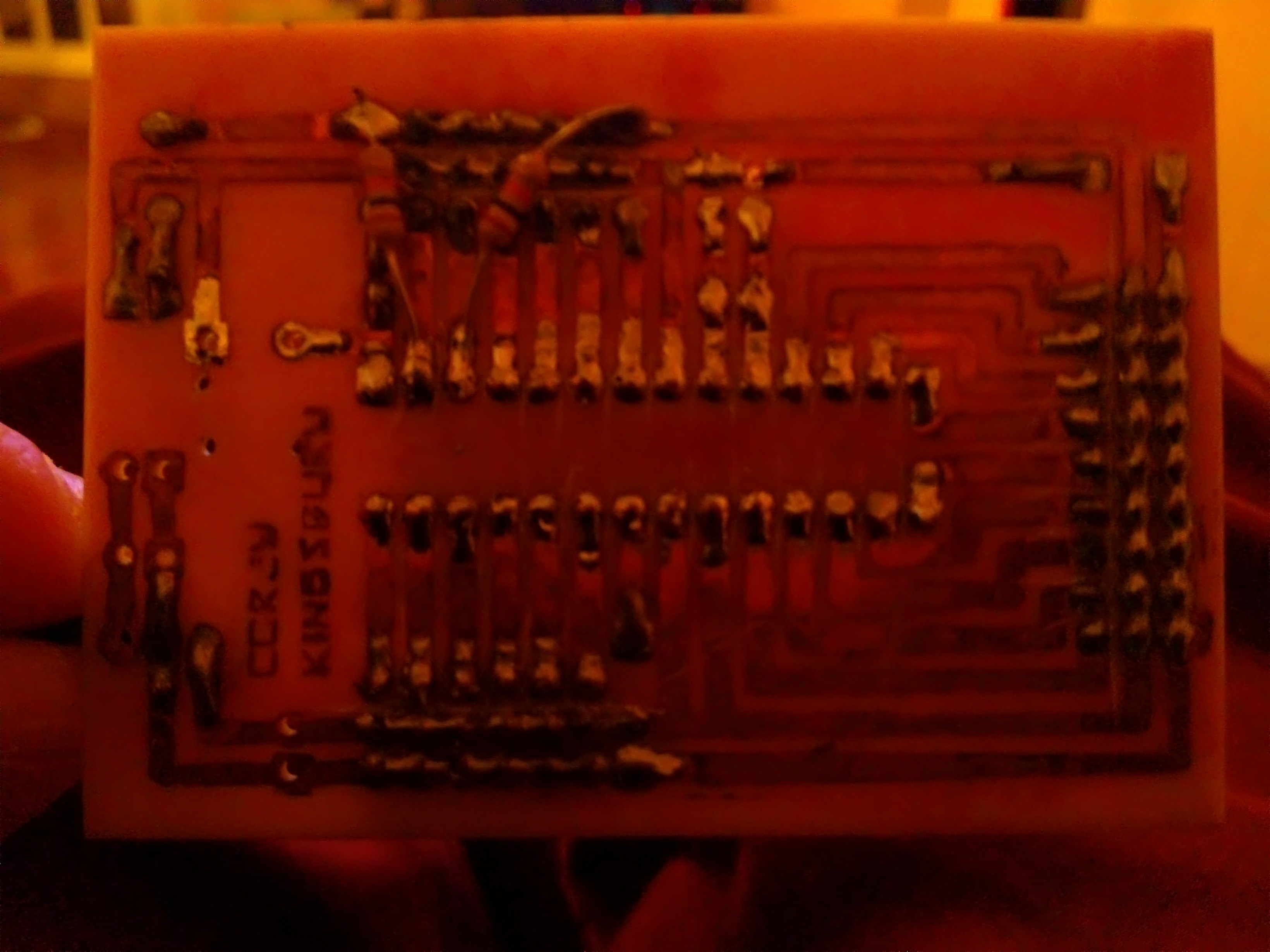
If I pull the atmega328p-pu and breadboard it, then I can upload just fine. I've attached pictures of the top and bottom of my board for reference. Thanks!

It doesn't look like that board has the "auto reset" capability, so a successful upload is dependent on careful (or lucky) timing of manually pressing the reset switch. Are you doing that?
The one on the instructables doesn't have a female header on pin 1, but mine does. I think that's what you mean. Mine has a female header on pin 1 and is also pulled high by a 10K resister. Also, I have added a 10K resister to pins 2 and 3 (tx and rx). Basically, the board is a duplicate of the breadboard with oscillator @ Use the FTDI Basic Breakout Board to program an Atmega328P-PU With Optiboot. | Modsbyus.com
minus the female headers.
Those photos are incredibly blurred. And the lighting?
Nice idea, how did you drill the holes? I tried to make a circuit board, that part went OK but drilling holes in a straight line was pretty-much impossible.
I can't comment on why you can't upload as it is more-or-less impossible to see what you have done exactly, sorry.
This page might help, perhaps: http://www.gammon.com.au/forum/?id=11637
Sorry about the image quality. Here are some new pictures. Better lighting and not blurry. I drilled the holes by hand with a dremmel.


I just looked over everything on the link you gave me. As far as I can tell I have everything in order based on what you have there. I have been to your site many times and used the resources there. Great site. I don't have a problem uploading a sketch on a breadboard, just on this board. From what I can tell, this seems to be a reset issue. If I remove the 328 and breadboard it, then program it with a sketch that has serial output, I can see the output in a serial monitor. So, I know that part is working. In the picture you will notice that I don't have a reset button. That is because I removed it to be sure the wasn't an issue with the button. However, before I removed the button I did try, for quite some time, to do a manual reset. That was also unsuccessful.
modsbyus:
The one on the instructables doesn't have a female header on pin 1, but mine does. I think that's what you mean. Mine has a female header on pin 1 and is also pulled high by a 10K resister. Also, I have added a 10K resister to pins 2 and 3 (tx and rx). Basically, the board is a duplicate of the breadboard with oscillator @ Use the FTDI Basic Breakout Board to program an Atmega328P-PU With Optiboot. | Modsbyus.com
minus the female headers.
The link you have shown using the oscillator is WRONG. The capacitors on the crystal should be 22pf not 22 microfarads.
Are you using the reset capacitor? If not, I think you indeed have a problem with resetting it.
JoeO:
The link you have shown using the oscillator is WRONG. The capacitors on the crystal should be 22pf not 22 microfarads.
Hopefully they are 22 pF. They look a bit small for 22 uF.
JodO: The caps are 22pf.
Nick: I am using the reset cap. It is in series with dtr on my breadboard.
Hard to say what is wrong then. Try measuring voltages. I don't suppose you have a scope or logic analyzer? I would be checking reset is being brought low temporarily, and that you see data on the Tx/Rx lines.
Also you could set the "CLKOUT" fuse and check that the clock is running.
I wish I had an oscilloscope! However, I don't. I will check that reset is being pulled low, but that wont be till tomorrow unfortunately. I just don't understand why it would pull low while on the breadboard but not on the board I made. We will see what further testing shows tomorrow. Till then, Thanks for your help.
Ok, so.. The reset pin is being pulled low. I have tried using various valued caps in series with the DTR and also tried using a 10K resister to ground with the series cap, and have gotten no where. If I remove the DTR wire from the reset pin then I get avrdude: stk500_getsync(): not in sync: resp=0x00. Any other suggestions?
Any chance you have Rx & Tx swapped?
I wish it were that simple. I have rx to pin 3 and tx to pin 2.
The chip calls pin 2 Rx. Depends on which "end" that refers to, however the outgoing data (to the chip) should be on pin 2.
I tried reversing the tx and rx lines, just to be certain. I get the same error that way too. (0x30)
Also, I have attached some pictures of the FTDI board and my arudino connected to it.


Did you say earlier if there was a bootloader on the chip already?
Yes, It does have the optiboot bootloader. This chip was pulled from and arduino Uno. I can program it on the breadboard just fine.
That is just odd then.
Can you post your schematic?