I am fairly new to the Arduino community so I apologize if this question seems obvious..
I bought a 5x7 Led Matrix from the store where they told me it was the anode version. I have tried to get it working but all i get are results of the board flashing or turning on all the LEDs and never the specific chosen ones. I have followed ALL 4 tutorials I could find online but all warrant the same result.
i use the led matrix without any other parts as shown in the arduino playground
That is one of the bad tutorials that can damage your arduino because there are no current limiting resistors in line with the LED. The lack of resistors won't stop it appearing to work though it will just do the damage. Note on the arduino page hey do mention that.
So it looks like you have not identified the wires into your matrix correctly. What have you done to ensure that the anodes and cathodes are what you think they are?
These? http://www.kingbright.com/manager/upload/pdf/TC20-11SYKWA(Ver1292470838.7)
So presumably you are driving the 7 anodes from something with current limit resistors, and sinking the 5 cathodes one at a time to turn on one column at a time?
Or are you driving only 1 anode high and only 1 cathode low at a time for much slower multiplexing?
Okay, one common way to tdo that is to drive all 5 anode hi or low, and pull one cathode, then repeat that for the next 4 columns quickly.
You will define some fonts, Imagine the letter A as a 7 tall x5 wide array with 1 = LED on and 0 = LED off:
So assuming an unused 8th bit that is always 0, each column could be represented as
01111111 = 0x7f
01001000 = 0x48
01001000 = 0x48
01001000 = 0x48
01111111 = 0x7f
So now you write some code that sends out a byte of data and 1 cathode control bit every 1mS:
void loop(){

// column 1
if (1mS elapsed){
all cathodes off
write anodes with 0x7x
turn on cathode 1
}

// column 2
if (1mS elapsed){
all cathodes off
write anodes with 0x48
turn on cathode 2
}

// column 3
if (1mS elapsed){
all cathodes off
write anodes with 0x48
turn on cathode 3
}

// column 4
if (1mS elapsed){
all cathodes off
write anodes with 0x48
turn on cathode 4
}

// column 5
if (1mS elapsed){
all cathodes off
write anodes with 0x7x
turn on cathode 5
}
} // end loop
Can you follow that? You are the driving the LEDs for a column at a time, and using persistence of vision to make the eye think any LED can be on at any time.
You can see how this would fit nicely into a loop, then expand from there to have the fonts predefined in an array where you would call up the letter/number in question, then expand from there to have say 3 letters in a 15 byte array and roll along to pick 5 bytes from that array for display (0-4, 1-5, 2-6, 3-7, 4-8, etc) to give the impression of scrolling text, and put new bytes in as needed to go thru your message...
Here's a video of my 8x32 display doing similar:
Scroll test of 8x32 LED matrix. Can hold up to 233 characters in SRAM. Will be ~40 more once I push 5x8 fonts out to PROGMEM.
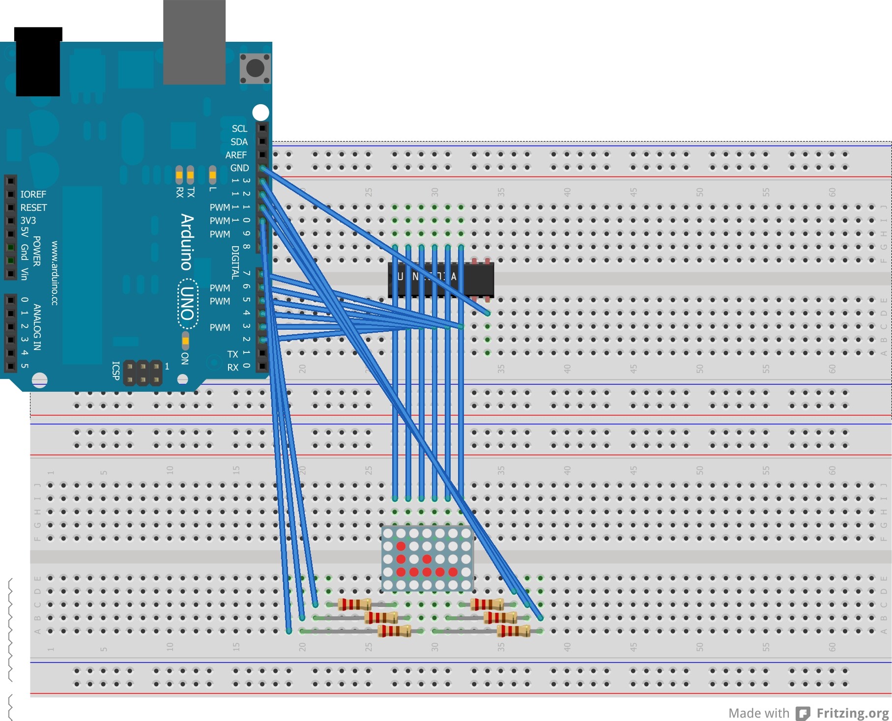
7 arduino pins with 220 ohm current limit resistors to the 7 anode pins.
5 arduino pins to 5 inputs on ULN2003A, 5 outputs to 5 cathode pins. Gnd to Gnd, COM is not connected.
Driving ULN2003 input high makes the output go low - only drive 1 input high at a time.
No you should not be doing. The point is that you have some memory that contains the bit pattern, then you apply that memory to the hardware. The code that does the refreshing does not change no matter what you display.
Read this:- http://www.thebox.myzen.co.uk/Workshop/LED_Matrix.html
could you explain why the matrix is wired incorrectly?
No I said the ULN2003 is wired up all wrong not the matrix.
I also said that:-
The outputs should go to the matrix not the inputs, the ground should go to pin 8 not pin 10.
That is the outputs of the ULN2003 should be wired up to the LED matrix not the inputs of the ULN2003 to the matrix.
You should connect pin 8 of the ULN2003 to ground, you have connected it to pin 10.
The ULN2003 looks a lot better.
Now the matrix is not wired like the data sheet is it.
The data sheet shows pins 9, 14, 12 & 8, 1, 7, 2 all being anodes. These anodes should be connected to the arduino outputs.
The data sheet shows pins 13, 3, 4 & 11, 10, 6 as all being cathodes these should be connected to your ULN2003.
Not much, that IC is a darlington transistor array so it already contains the base resistor you would need if you used a normal transistor. It is smaller so there is less wiring up.
The LED wiring is off still.
Note that the pins are shown as going across the short length of the body. So you may want to plug the chip in across the middle divider.
I have labelled them A1-7 for the anodes,
and C1-5 for the cathodes.
A1 is pin 9
A2 pin 14
A3 pin 8
A4 pin 4 (also available on pin 12)
A5 pin 1
A6 pin 7
A7 pin 2
C1 pin 13
C2 pin 3
C3 pin 4 (also available on pin 11)
C4 pin 10
C5 pin 6
If you look on the bottom of the part you may see a 1 next to one of the corner pins.
Plug it in and drive the output pin for C1 high (display pin 13) and for R1 low (display pin 9) - should see the corner LED turn on. If not, rotate the display 180 degrees around and try again.