I have a project, where a DC motor (via H-bridge) is supposed to be controlled by two buttons 'up/down'. Every time a button is pressed, the motor is supposed to turn x-amount of turns. Because this project will be used eventually in a race car, I decided to come up with my own rotary encoder. The motor has a attached gearbox. One of the gears near to the motor (higher rpms) is made of plastic. I drilled two holes in it, aligned exact opposite to each other. Then I pressed a tiny (4mm) magnet in each hole. I'm using two magnetic field sensors to spot the magnets. The two sensors are offset by a few degrees. I have put the usual R/C circuit on the output of those sensors to avoid noise. The siganls are eventually inverted by a 7400. The tow signals are fed into interrupt 4 and 5 of a Arduino MEGA. The SOftware is pretty straight forward. I'm using both interrupts in the 'CHANGE' mode, reading the two signals at first thing in that interrupt via 'digitalReadFast' (from digitalWriteFast.h) for low/high and high/low transitions. Everything seems to work. However, the positions are not exact repetitive. My scope (two channels) shows signals A and B absolutely perfect. No noise, perfect offset. Didn't know how to help myself other than writing a 'built in scope' directly into the software. I'm writing the state (after reading the two inputs) for every interrupt call into a array with increasing index. On a push of a button those measurements are spit out via serial onto the monitor. I found out that that the interrupts for one channel every now and then are called twice in a row. With that given (perfect looking) signal A/B the two interrupts are supposed to be called intermitted. Most of the time this is the case - but unfortunately not always. That of course screws up the counting and along with that the position.
Does anyone have an idea what the cause could be? I doubt that the software is a problem. I’m writing C/C++ code on a professional base since almost two decades. But who knows … For now I’m near the end of my ideas. What I could/will do is to write a similar program for another uC (I have a couple of R8C’s here) and see how that works.
By the way, in that Arduino-program, I tried to eliminate almost everything that could be of interest, stripped the program down to its absolute limits, just leaving the two interrupts plus motor left/right + speed in it. No change on the problem with that.
It's possible your RC circuit you're using for filtering is doing more harm than good by slowing down the signal and causing "bounce". An RC filter is not a really good way to get rid of bounce unless you follow it with a Schmitt trigger squarer like a 74xx14.
So...things to try:
Get rid of the RC circuit
Use less filtering (smaller R and/or smaller C)
Replace 74xx04 with 74xx14
And this effect could definitely be fast enough that you wouldn't see it on the oscilloscope at the time scales you are looking at. You may be able to see it occasionally at the output of the 74xx04 (if I'm correct) if you really zoom in on the timescale of the oscilloscope and look at just one edge.
--
The Gadget Shield: accelerometer, RGB LED, IR transmit/receive, speaker, microphone, light sensor, potentiometer, pushbuttons
What hall effect sensors are you using? If they have logic output (not analog) then you must not add the RC filter, its already digital and these sensors all have hysteresis built in. Non schmidt-trigger logic gates are high-bandwidth high-gain amplifiers that can turn slowly ramping waveforms into bursts of oscillation in the 100 MHz range - logic inputs must either be driven with fast switching (logic) waveforms or be schmidt triggers.
We all forget that those "digital chips" are really amplifiers. They really do have a leading and trailing edge, and if you operate in that region they are amplifiers and can oscillate and glitch and do all sorts of nasty things.
I have seen these problems for many decades now as designers forget to allow for the ramps on the leading and trailing edges.
First of all: thanks for taking your time to read this and even more for your thoughts.
@MarkT I'm using the TLE 4905L. It has basically a schmidt-trigger with an open collector output stage.
@ RuggedCircuits
To get a 1/0 signal, I'm pulling it up with 4,7k to +5V. If the output-transistor is open, the logic 1 is only driven by this pull-up, making it vulnerable to noise, that's why I have put that R/C into the circuit. Without it it is even worse. Judging from scope, the signal after the R/C has pretty much round edges (as an effect of the R/C) but still steep enough to not cause timing problems. This signal is then formed perfectly square by an 7400 (will certainly not go into ‘production’ with that dinosaur ).
And this effect could definitely be fast enough that you wouldn't see it on the oscilloscope at the time scales you are looking at.
That’s my biggest fear. My scope only allows to widening by factor of 10. Even with that magnification I don’t see any spikes. But I’m getting that fuzzy feeling that there are some – just too short to see them. What supports that impression is that the ‚build in software scope’ shows several multiple calls/triggers of the same interrupt - but the subsequent reading of the pin-value gathers the same value as by the call before – which is logically impossible because the trigger is defined as CHANGE. But if it was only an extremely short spike, the subsequent reading of the pin-value would probably not catch this which would explain this behavior.
That device is spec'd for rise/rall times of 1us for a pull up of 1k2 and 33pF of load - it needs feeding directly into a schmidt trigger to be on the safe side. If you have it at the end of a long lead then make sure the pull-up is a lower value like 1k and place the pull up at the Arduino end of the cable, not the hall-sensor end. Do you have long leads BTW? Are they shielded or twisted-pair?
I have double checked the specs this morning and thought about that pullup for a while. I’ll try this evening to place the pull-ups near the Arduino and possibly use shielded wires. The length at the present is about 2ft. In the final version (controlling all four shock absorbers in a race car from the cockpit) the length of the cable might be even longer. Shielded versions are probably the best choice. How about (for the test bench and later something similar) if I put the R’s and C’s plus a 7400 (two gates inputs tight together) very near the sensors on a small PCB. Would the (output-)signal from the 7400er be more immune?
Also, I’ll put together tonight a quick&dirty counter, hoping to ‘see’ those false pulses this way.
Running unshielded wires near motors is asking for interference... shielded coax or shielded twisted pair are prefered - the power to the hall sensor needs some decoupling at the hall sensor too really. 2 foot isn't that long though. So long as you don't route the sensor wires with the motor wires I would have thought you would get away with it.
I trust the motors run off separate power from the sensors BTW?
I have plenty Cat 5/6 cable here which I’ll use to replace the signal wires. And I admit, although I do this almost everywhere on my breadboard (near ICs), I forgot to decouple the power to sensors, I’ll add this too.
The last question I can answer with a big yes. I just bought two regulated power supplies, on is dedicated to power the H-bridge.
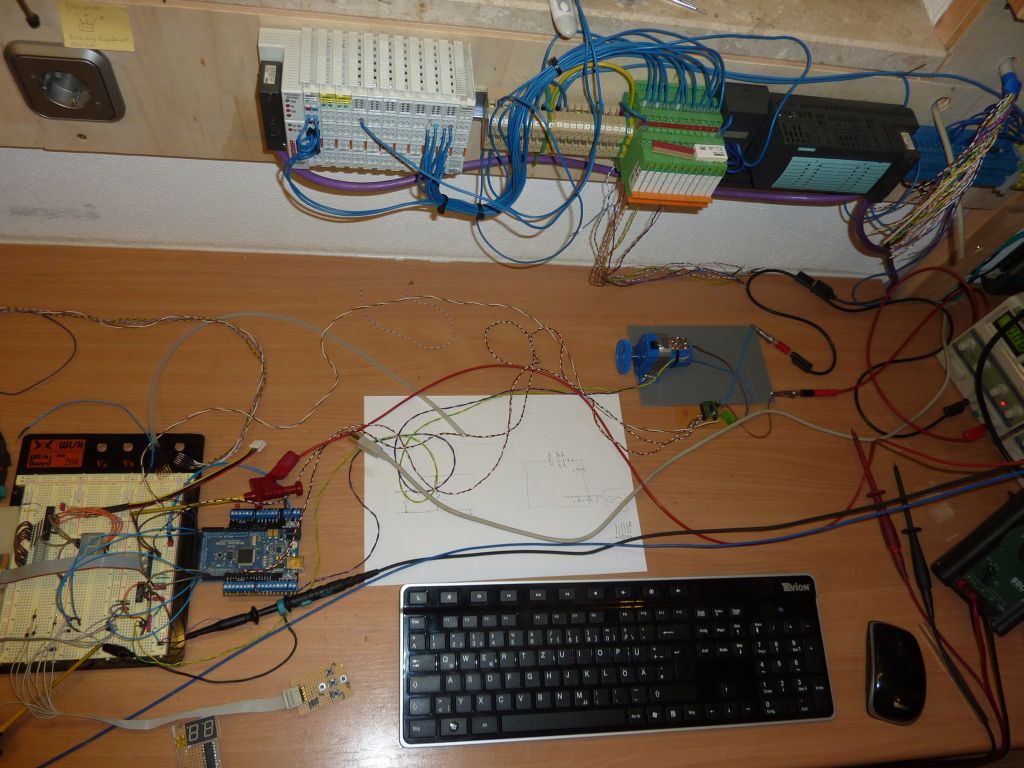
Just thought, some images would make thinks clearer - and added three of them.
The motor is just a test bench for the sensor; the final setup will be considerably different (small motor, gears and sensors are gonna be packed together in a tiny plastic enclosure).