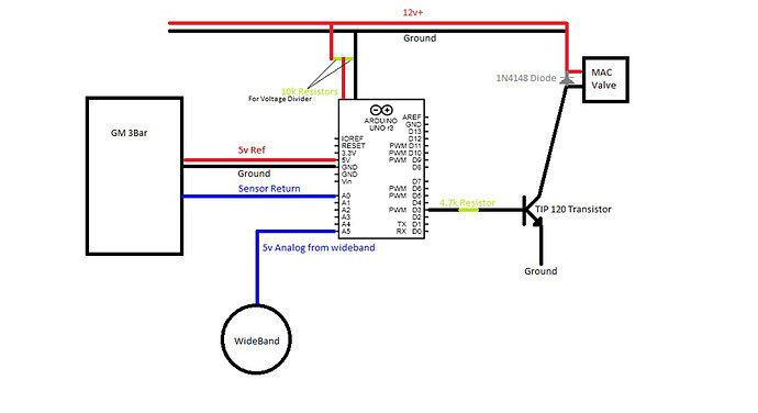
I'm new to Arduino, and programing in C+, but not programing in general. This is my first project, and am looking for feedback from a more experienced audience. So here goes:
I set out to create a closed loop boost controller for a automotive application, those of you not familiar this the concept this is a rough description, the controller essentially pulses a solenoid valve installed inline on the vacuum/boost hose from the turbocharger to the wastegate. It is intended to "hide" boost from the wastegate to keep it closed, which in turn builds more boost.
My Diagram is attached, and it seems to work on the desk, I have not installed it in a car yet. Mostly I'm curious about the quality of my code, is this the cleanest most efficient way to write it? Does anyone have suggestions on how to improve it?
#include <PID_v1.h>
//Define Pins used
const int MapPin = A0; // Map sesnor pin
const int MacPin = 3; // Mac valve pin
const int WBPin = A5; // Wideband pin

//Set desired boost level and define Pid variables
double TargetBoost = 250; // 250kpa is target boost level
double MapKPA, PidPWM;// Initialise other PID variables
const long sampleRate = 15;// Pid sample rate

// Pid tuning parameters
const double Kp = 7; //Pid Proporional Gain. Initial ramp up i.e Spool, Lower if over boost
const double Ki = 20; //Pid Integral Gain. Overall change while near Target Boost, higher value means less change, possible boost spikes
const double Kd = 0; //Pid Derivative Gain. Not Sure what to do with it.....

//Load PID controller
PID myPID(&MapKPA, &PidPWM, &TargetBoost, Kp, Ki, Kd, DIRECT); //Initialize PID with our variables

//Set other global variables
unsigned long LeanTime;
float Lean = 0;
float Cut = 0;
float AF = 0;
float Atmo = 0;

void setup() {
  //Serial.begin(9600); //debug uncomment to debug
  Atmo = analogRead(MapPin) * (315.0 / 1023.0); //Read Atmospheric pressure and convert to KPA
  //Pid Stuffs
  myPID.SetMode(AUTOMATIC);
  myPID.SetOutputLimits(0, 180); //Mac valve lower duty cycle limits 180 Closed, 0 Off
  myPID.SetSampleTime(sampleRate); //PID's sample rate in milliseconds
  TCCR2B = TCCR2B & B11111000 | B00000111; //Set pin 3 and 11 PWM frequency to 31hz
  pinMode(13, OUTPUT);
}


void loop() {
  //BenchTest
  /*if (MapKPA < TargetBoost) {
    MapKPA = (MapKPA + random(10));
  }
  else {
    MapKPA = (MapKPA - (100.0 - PidPWM));
  }*/

  MapKPA = analogRead(MapPin) * (315.0 / 1023.0);  //Read map Pin and convert to KPA
  AF = ((analogRead(WBPin) * (5.0 / 1023.0)/0.625) + 10.0);//Read wideband and convert to a/f ratio

  if (AF > 12.1) {
    Lean = Lean + 1; //add to lean counter
  }
  else {
    Lean = 0;//Reset lean counter becuase rich
  }
  if (Lean == 1) {
    LeanTime = millis();//Log initial lean reading time
  }
  if (((Lean >= 2)) && ((unsigned long)(millis() - LeanTime) > 250)) {//Check if lean for more than 250ms (.25 seconds) and lean more than 2 loops
    Cut = 1; //cut boost if too lean for too long
  }
  else {
    Cut = 0; //dont cut boost becuase rich :D
  }

  if ((MapKPA < 100) || (Cut>0)) {//Keep valve from clicking when not in boost or cut boost if too lean
    PidPWM = 0;//Dont pulse if not building boost or wideband is lean
    //Serial.print("Boost Cut");//debug
    digitalWrite(13, HIGH);
   }
  else {
    myPID.Compute(); //Execute Pid and produce a pulse width if above 100kpa and not lean
    digitalWrite(13, LOW);
  }
  analogWrite(MacPin, PidPWM); //Energize mac valve

  /*
  //--------------------Debug--------------------
  Serial.print("--------------------PW=");
  Serial.println(PidPWM);
  Serial.print("--------KPA=");
  Serial.println(MapKPA);
  Serial.print("Target=");
  Serial.println(TargetBoost);
  Serial.print("AF=");
  Serial.println(AF);
  Serial.print("Cut=");
  Serial.println(Cut);
  Serial.print("Lean=");
  Serial.println(Lean);
  Serial.print("LeanTime=");
  Serial.println(LeanTime);
  Serial.println(" ");
  delay(250);*/
  }
