Trying to power up an Arduino Due by the power barrel jack. No ON light, all dark. Otherwise works fine powered up by the USB.
Measuring 12.3VDC at the power in jack plugged in, but 2.7V at VIN versus GND. Is that bad? Defective L6? The reference schematic says L6 is a MH2029-300Y, a "High Current Chip Ferrite Beads". The power cube is 9VDC 800mA, center positive, but I've tried 3 others (9VDC to 12VDC nominal, 10-16 measured).
Shots in the dark
(After looking at the schematic) check to ensure:
D1 is inserted properly (if inserted backwards, then the wall-wart supply will be shorted out).
Check the polarity of D3, D4 as well.
PC1 is inserted properly (Electrolytic caps will fail if inserted backwards).
IC2 is inserted properly, with no solder shorts on the pads.
L6 is well soldered.
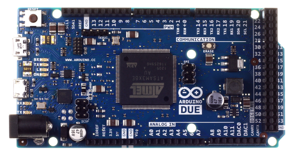
See a nice picture here:
See attached pic for locations.
The fact that your wall-wart supplies are measuring so high is an indication that they may not be delivering current to the board (bad jack?, bad pcb?).
Really check out IC2 and L6, as it sounds like there may be an open-circuit somewhere on the Vin side of IC2.
D3, D4, where are they? Was that in something you sent me, I could not see. The big black packages north, and northwest of IC2 are oriented the same as in the photo.
PC1 polarity, check (matches photo)
IC2 no shorts. Can barely make out marks in photo but they seem to be oriented same, "SFED" turned 90 degrees clockwise
L6 reflowed solder
Still no life from the jack. Wall-wart power drops from 12.6V to 12.2V (nominally 9V). Measuring 9.4V across L6, and 0.3ma through the jack. Doesn't sound right for a ferrite bead? Seller offered to swap.
D3, D4, where are they? Was that in something you sent me, I could not see. The big black packages north, and northwest of IC2 are oriented the same as in the photo.
That sounds right.
IC2 no shorts. Can barely make out marks in photo but they seem to be oriented same, "SFED" turned 90 degrees clockwise
That sounds right too (except I read it as "SFEB"").
How about PC2 (the other 47uF/16V electrolytic cap nearby)?
Measuring 9.4V across L6, and 0.3ma through the jack.
Sounds like an open circuit to me (I'm not sure where that 0.3mA is going though).
To be clear, with the positive voltmeter lead touching the left-side of L6, and the negative voltmeter lead touching the right-side of L6, you measure +9.4VDC. L6 is not hot-to-the-touch. Then all signs point to L6 either not being soldered properly, or L6 has failed.
The resistance of L6 should be small (the datasheet says that it's 0.025 ohms). If testing it while it is still connected to the circuit, then place the positive lead of your ohmmeter on the left-side of L6, and the negative on the right (otherwise you may be testing the diode next door). Do not have the power supply connected when testing the resistance of L6. A high resistance means that L6 is kaput.
To attempt to get the board to work, you could remove L6, and short the two pads that L6 was using to each other (with a short piece of wire, or a solder-blob). L6 is there as a simple filter, and the circuit should function if it is replaced with a 'short'. (to be kind to the circuit, use a nice regulated desktop DC supply if you have one).
**The danger ** - Suppose L6 has failed because there is indeed a short farther down in the circuit. By shorting-out what was L6, you would then be applying the full-capability of the connected supply to the sneaky, yet-undiscovered, short. Possibly releasing the magical blue smoke held inside the offending component.