I'm sure I'm using the wrong vernacular, I apologize. Every related topic I found in a search was focused on vocabulary instead of answering the question.
I have a piece of equipment that has some stepper motors, I'd like to use the equipment but the control is only partially functional. The motor driver turns the motors when manually signaled, but originally the motor driver interfaced with a PC with some kind of motion control board that sent pulses to the motor driver for more advanced movement. I'd like to use an Arduino to send pulses to the motor driver but it appears that the switching is done using negative signals with a common positive (this is where I'm sure my vocabulary may be incorrect, again I apologize).
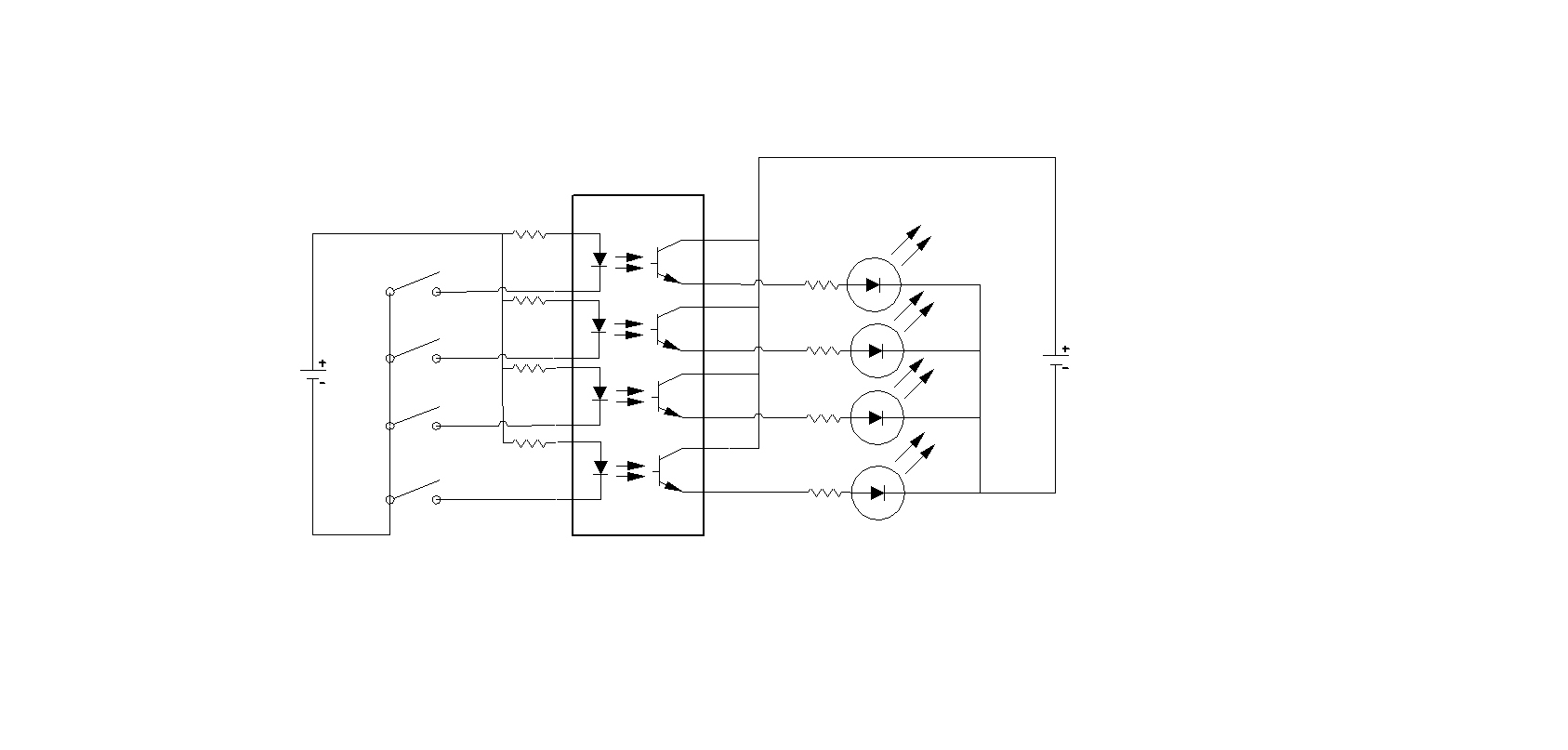
The attached schematic approximates the portion of the circuit I'm concerned with. The anodes of the opto-isolators on the motor driver board are tied together and the cathodes are switched. I drew the circuit controlling LEDs because I had a symbol for an LED and didn't have a simple symbol for a stepper motor control circuit. I'd like to replace the switches shown in the schematic with the outputs on an Arduino.
What hardware do I need to invert the polarity of an output? If the pulses weren't in mhz I'd use a relay, but given the application I believe I'll need something that will be able to operate at a moderate frequency.
Are you sure that negative pulses are needed ? Perhaps the signal is once more inverted after the opto-couplers ?
I have not heard yet of a Stepper library that uses an inverted signal.
This is the Arduino default library: Stepper - Arduino Reference
You could make a copy of the that Stepper library and invert the signal.
You show 4 opto issolators in your diagram. How many motors do they control?
There are a few ways you could tackle this. It really depends if you want to leave the manual system in tact. Even if you do, there's nothing stopping you from altering the circuit to put the switches on the anode side of the optos. At the end of the day they're just LEDs.
BTW What voltage is being supplied to them at the moment?
Peter_n:
Are you sure that negative pulses are needed ? Perhaps the signal is once more inverted after the opto-couplers ?
I have not heard yet of a Stepper library that uses an inverted signal.
This is the Arduino default library: Stepper - Arduino Reference
You could make a copy of the that Stepper library and invert the signal.
I'm fairly certain that the polarity is inverted after the opto-isolator with a common ground, but for whatever reason the positive is common before the opto-isolator. A negative signal is needed to activate the led in the opto-isolator. I don't need to invert the signal (ie turn a high signal to low,) I need to change +5v to -5v.
KenF:
You show 4 opto issolators in your diagram. How many motors do they control?
There are a few ways you could tackle this. It really depends if you want to leave the manual system in tact. Even if you do, there's nothing stopping you from altering the circuit to put the switches on the anode side of the optos. At the end of the day they're just LEDs.
BTW What voltage is being supplied to them at the moment?
I show 4 opto isolators because there are 2 ICs with 4 banks and another IC with 2 opto isolator banks. For simplicity I only showed part of the circuit rather than showing everything. The motor driver board controls 3 motors with a direction and pulse signal plus various I/O for limit switches, indicators, etc. The board has a 20 pin header for IO with a positive voltage applied as a common, my goal is to leave the board unaltered and perform any signal modification externally because it's easier to splice into the ribbon cable that connects to the board than to try and move traces on the board. I don't intend to re-engineer the motor control circuitry, if I can't easily present the correct signals to the IO connector on the motor driver, I'll scrap the board and replace it with one of the many available stepper drives that use a positive signal and negative common. I'm just trying to avoid having to gamble on buying Chinese electronics or pay through the nose for a drive from a reliable domestic distributor.
As far as the manual controls and misc I/O are concerned, I plan on replacing them, all I want to be able to do is supply a direction and pulse signal for each of the 3 motors. The control system operates at 5v DC, the stepper motors are powered by 24v.
You do not need to change the polarity at all. Just connect the common line to the 5V line. The LEDs will be turned on by what is known as current sinking, this is a common practice in professional circles.
There is no need for a common ground.
Hi, can you tell us the model and type of motor driver it is.
On your diagram you haven't noted what each of the inputs does.
Even a picture of the device will help.
Aside from the ways stated above (which I would do) of reversing the polarity in code, you could use a simple inverting transistor stage, In essence drive the base of an NPN low power transistor (for example BC108) via say a 2.2K resistor, ground the emitter and connect a 1K resistor from +VE to the collector. When the pin is high, the transistor will go conducting and the collector voltage will be 0.7V or less. When low the transistor will be off, and the collector will be +VE.
Grumpy_Mike:
You do not need to change the polarity at all. Just connect the common line to the 5V line. The LEDs will be turned on by what is known as current sinking, this is a common practice in professional circles.
There is no need for a common ground.
Indeed the whole point of optoisolation is to prevent grounds being commoned together,
since in industrial environments with high power equipment grounds are not the same everywhere,
by many volts even.
The standard step/direction circuitry responds to the rising edge only of the step signal, so if
the signal is a narrow pulse it won't matter whether the receiving optoisolater is active high
or active low since there is exactly one rising edge in a narrow +ve-going pulse and exactly
one rising edge in a narrow -ve-going pulse. The pulse should be 10us or so to deal with
slow optoisolators.
Okay, I may have had a fundamental misunderstanding of how arduino outputs work. I had thought that a high output was +5v and a low output was an open circuit like in a blade switch. If I understand correctly a high output is +5v and a low output is at or near 0v. So, I can connect output and common as usual with a common ground and things will work just fine, all I have to do is remember to use a high output for off and a low output for on.
You connect the common of the optocouplers to +5V and the Arduino output pins to the inputs of the optocouplers (Arduino pin is used as active LOW).
An Arduino pin can be input or output. When it is output, it is either HIGH which is +5V (about 20mA source current) or LOW which is 0V (about 20mA sink current).