FTDI basic & serial upload to atmega328P breaduino out of sync

Edit:Solution. I used the usb tiny isp to upload a program before trying to hook up the atmega328p to the FTDI basic board and it somehow caused an error which would cause the FTDI not to work. I reloaded the bootloader and tried the FTDI straight away and was golden. I also had to switch away from uno and go to duemilanove due to the opti bootloader. Don't forget that the FTDI basic board requires a reset cap in series with the reset pin!
Special thanks to spcomputing.

Win7 32bit
Protoboard arduino with atmega328P (both duemilanove & uno)
I can only upload with my USB tiny ISP parallel programmer(blink and fade sketch confirmed).
The FTDI basic board does not sync. The TX LED flashes 3x and gives me the out of sync error. Rx never flashes.

Well this is about hour 6 of lurking google for answers and I am irritated/tired so I will do my best to explain everything I have tried.

I can upload to the board with my ISP so the breaduino is wired correctly.
*as for the FTDI basic board, TX(FTDI) goes to RX(atmega) (transmit to receive and vice versa, I also tried TX=>TX Rx=>Rx while being desperate). Correct pins have been checked repeatedly.

I am aware that the uno no longer uses FTDI so I've tried Bootloading the atmega with both Duemilanove&Uno bootloaders.I have tried all of the stuff in this post on both bootloaders.

The com port matches the port listed in my device manager.

The board was correctly selected for both bootloaders.

The Power LED was functioning

The Arduino IDE is the most current version.

The drivers were tried from the arduino folder, FTDI website, and auto search. None worked.

  • I could only find FTDI drivers. Some forums mentioned one specifically for the uno but I could not find it to try (I am using FTDI after all).

I have tried a .01uF and .1uF cap in series with the reset pin on the FTDI board.
*This came from a random page in one of the countless forums

I have spent an hour trying to manually reset before uploading (mostly on uno) but I can see the board reset because the blink sketch is running 1000 on 10000 off.

I have tried multiple atmega328p chips.

I have aimlessly tried different baud rates and other advanced settings through the device manager.

I own two teensys and an uno. I could just develop with my uno and burn atmega328p(s) with the ISP but I really don't want to chunk wasted time and money. I have the components for 20 protoboarduinos. I was planning on giving a few away to classmates.

The chip is indeed an atmega328p-pu and not an atmega328-pu (I bought the 328 by mistake first time around and gave up on them)

So to summarize, the FTDI board will not work and without it I can not use the serial monitor to debug. I have Two FTDI boards .... They both do the same thing, and at this point I'm willing to ship you my favorite high gravity lager as a thank you for successfully helping.

any thoughts?

SouthernBinary:
... I'm willing to ship you my favorite high gravity lager as a thank you for successfully helping.

any thoughts?
Ummm... high gravity... cold ferment... Yum.

Okay, try this before we go through the list. Find blink again and upload to the "boarduino" (I assume it is a Breadboard Arduino and not Lady Ada's "Boarduino"). When the IDE goes through the verification process, put your finger on the reset button (don't push it yet) and watch for the "Binary Sketch Size" to pop up in the terminal window, then look at your FTDI leds and push the reset button. Watch the Rx leds for two pulses andthen release the reset button. Does the Tx kick in?

My apologies for saying boarduino, and I assume you mean Tx blink 3x since it is trying to transmit. Tx blinked twice, I released, blink sketch (isp programmed) started as third Tx blink occured. Rx did nothing. Out of sync.

Also I removed the restart wire and cap since you have me doing it manually. I'm also currently bootloaded with the uno bootloader.

My bad on the Rx confusion. Yes, if your board is NOT ready, it will blink on the FTDI 3x and timeout. I spent a week learning the manual triggering process. I was just ruling that out.

Okay, sanity check. Look through this document and let me know what does not look right:

Finally, after you burn your bootloader, do you have an LED on the board to execute the "Blink" sketch and does it blink (Built-in to the Bootload Process)? You should have a blinking LED at the end if your board is bootloaded properly(Okay, I have Breadboard 1284p(s) that HATE Optiboot and will blink, but you can not communicate with FTDI).

If this is OK, then we will need to go back to bootloader. Optiboot can have issues. If you bootload with the non-Uno bootloaders, you can eliminate the Optiboot issue.

I will see if I can find some actual board layouts for you to review.

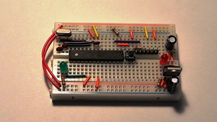
That rat nest of a tutorial is hideous. I'll attach a picture of my setup its simple. I removed the 5V regulators and only rely on usb power, and I attach the breakout board manually. Ive checked the board against

http://itp.nyu.edu/physcomp/Tutorials/ArduinoBreadboard/
& the atmega datasheet.
they are right.

Will FTDI even work with optiboot?

I am a little confused with "an LED built into the bootloading process". First I burned the bootloader, and then I held Shift+CTRL+U to upload to the board with the programmer.

There is an LED on the board. I hooked it up to atmega pin 3 for blink test and pin 15(PWM) for the fade test. Everything is perfect with the ISP alone. I do not however have an led hooked to the default arduino 13pin(aka pin 19 on atmega328).

The board should be boot loaded properly because I could not correctly upload sketches when I tried without burning the bootloader (blank atmega328 chip). The led would blink oddly but would ignore code when I tried to change the duration.The fade sketch would not work at all.

and again I did try the FTDI with the duemilanove bootloader and it was still out of sync. Would you recommend a different board type/bootloader?

I got a few other things to try. I'll keep tinkering until I hear back from you. Thanks btw.

ps. I bookmarked a page on 1284ps. I may end up needing 128k flash for my garden control system :sunglasses: much love! I was planning on using two 328ps if i went over the 32k flash x-( no bueno

"I bookmarked a page on 1284ps"
and I have a board for that :slight_smile:
See the my signature link for different variations.

  1. thanks but the price is too high. I would rather buy more protoboards and components than leave a high dollar board in my project. The teensy++ has the same flash space & IO for $24. By December I will have my BS degree in Engineering Tech. I'll leave PCBs to the hobbyists, at least until I get my photo transfer method down to make my own :grin:

Back to troubleshooting

I have heard that the new Optiboot is supposed to work. I will test it out someday.

Attached are layouts using that "rats nest". I am working on simple diagram of it so that do not have to torture people anymore. Configuration is 16MHz Duemilanove bootloaded.

No, the FTDI will only work after the bootloader is installed. When the standard Arduino bootloader is burnt, a version of the blink sketch is installed as well you let you know the MCU is alive and well blinking D13 (Pin 19). The blink will need to be steady, ~500ms on and 1000ms off. Putting Optiboot on a 1284p gave me a "tweeky" flash on the D13 and sounds exactly like the non-communication issue you are having. I used older version and it worked. Anyhow see if you can upload the Duemilanove bootloader (with the ISP Tiny)with a led and resistor on pin 19.

BTW, what kind of crystal is that on your board?

The crystals I got from digikey about a year ago when I first started picking up on breaduinos. Its the right Freq 16MHz. I will admit that most of my testing was on the uno's optiboot and I may have crossed a brain wire on what I did and did not try something. So, I will retrace my steps and see if I overlooked something.

TX=>RX
Rx<=TX
For the FTID to atmega right? I need to rule that out as a possible mistake so I'm not switching them over and over.

Oh and sorry for my blurry picture. I only own an Iphone as a camera.

Fritzing is a good program for bread board layouts by the way.

TX=>RX
Rx<=TX
For the FTID to atmega right? I need to rule that out as a possible mistake so I'm not switching them over and over.

Yup, after we confirm the bootloader with the ISPTiny on MOSI, MISO, SCK, Reset and power. Make sure the Reset is directly to pin 1 and not the Auto Rest Cap.

Fritzing is quite good. My diagrams of this project are going to be line art though :wink:

okay pin 19 is blinking .5sec on 1sec off with the duemilanove (i hate that word) bootloader on pin 19.

Afirmative on the cap reset. You need to make sure your not powering the board with 10V as well (5v FTDI 5v ISP=magic blue smoke<-- for the lurkers).

Excellent.

Now, disconnect the ISP and hook the FTDI back up without the reset to the capacitor. Upload the regular Blink sketch.

We will manually reset on sketch size and two blinks and release the reset button again.

HAH the stupid thing works! .... hmmm now to explain that error! I bet if I try to upload blink with the isp and then use the FTDI it wont work...

...HAH it was because i had uploaded using the ISP tiny programmer.

okay this was the problem.
bootloaded>uploaded different program with ISP>failed FTDI upload!
Bootloaded>BUENO FTDI upload!

I thought that may have been the problem when I woke up this morning.

"thanks but the price is too high"

Yes, the original Bobuino was jam packed with parts and that did run the price up.

The bare boards for the latest 1284 Mini and the recent 1284 style duemilanove are really inexpensive, like $2.50 and $4.50. Really just the cost of the boards and US mail.
Populate them as your needs dictate. Mostly thru hole or larger SMD parts for easy assembly.

hmmm i wonder why using the ISP tiny to upload a program breaks the FTDI. Thanks for the help and direction. Helping me rule out a few "what ifs" really lowered my stress level man.
pm me with an address if you want that lager.

I have actually had a bootloader that installed and the FTDI tripped (the internal fuses?) something and it would not respond as well. I have read that some high/low fuse settings can be an issue on certain bootloaders. Next time, we will play with AVRdude :wink:

Try hooking the auto-reset capacitor to the DTR pin if you haven't already and see if it works.

I am curious about the pros and cons of a bare bones board vs a more populated board. I also read something about needing extra circuitry for the analog power reference, but I have no idea what the circuitry is or what needs an analog power reference.

I had it working by the time you told me to take out the cap. It just took me too long to post because I was identifying the error. I had left the auto reset cap in place when it was working.

I just tried it without the restart cap and it would not upload with FTDI. I put the cap back in and it was golden.

Actually, you had your analog reference hooked up (could use some 0.1uF for decoupling) and it can come in handy when you run on batteries. My examples did not have AREF connected. There is not too many parts, just some 100uF caps to clean the noise from wall power jacks and a 7805 regulator. Full size breadboards are nice to run a uC and sensors in one package. The original layout came from oomlout.org and I thought it was a decent layout.

Populated boards are handy for the Arduino shields and when trying to not scare a non-electronics type.

I think the only real value of barebones is the knowledge of how the basic components work and it is a repairable platform for when you do something a little more dangerous :smiley: ... SMD repairs suck.

Well, if it works, it works. That is quite a large 0.1uF reset cap.

The cap puts up with 50V according to the numbers written on it. It was a radio shack last min necessity purchase. Its only .1uF but its a hefty .1uF lol. Its all they had.

I do have a regulator with filtering caps I soldered together on a protoboard. Does the AREF need one as well if the 5 V is already regulated?

Heh I have a power jack I was planning to use for 5Vsupply. So the jacks have noise? I figured they would be filtered, and where does the cap go for AREF? Parallel or series?

Wish me luck, My garden project includes an RTC module, SD module, frequency to light converter(AtoD), a humidity temp sensor, and a few relays and relay-H-Bridges to run a motor to raise and lower lights. I'll be circumference counting with a home made encoder wheel as well. I may see a 1284p in my near future. Now if only I could get my classmates to stop with the hippy references lol.

Yeah in my opinion SMD should be left to specialized ovens instead of soldering irons and jewelers loupes.
I tried SMD with a normal tip once and kicked myself in the behind.