I'm trying to create an RPM measuring device, similar to those found in bike computers. Now, I'm doing this as a CS student and haven't had much luck finding help in getting the electronics working for this project.
I have 3 types of Hall Effect sensors that were available to me (I can order different types if anyone has suggestions).
Here are the 3 types I have:
180 Gauss Latched:
180 Gauss 1 Polar Latching
60 Gauss 2-Polar Latching
Magnets:
I am having difficulty wiring these with an Arduino. I'm not sure whether I need to add a resistor into the connection between the sensor and the Arduino, as in the ReadingRPM section of the Arduino Playground seems to suggest (but perhaps this is only for use with the PC fan setup).
I have tried all the sensors, wiring them with or without a resistor, with the ReadingRPM code. Am I using sensors that are too insensitive, or magnets that are not strong enough, or am I just completely getting the wrong end of the stick about how the sensor works?
My understanding is: magnetic field -> induce current in sensor -> pulse the control wire of the sensor (this is the middle wire, right?)
As you can no doubt see, I'm no electronics expert! But this seemed like something that should not be overcomplicated to set up, but has proved to be. This suggests to me I'm missing something that I probably wouldn't if I had a good electronics background.
Could someone please suggest some remedies for me? I cannot find any 'novice' instructions for wiring a Hall Effect sensor with an Arduino, and I don't have a bike computer sensor to hand to use instead.
If anyone has any suggestions at all regarding the sensors, the wiring, or the magnets, please let me know, I would be extremely appreciative. I'm sorry to ask for spoon feeding but my attempts to get this working have failed and are beginning to become frustrating!
My understanding is: magnetic field -> induce current in sensor -> pulse the control wire of the sensor (this is the middle wire, right?)
Amended: change in magnetic field -> induce current in sensor -> pulse the control wire of the sensor
The magnet moves past the sensor, and the sensor's motion through the magnetic flux pattern creates the impulse. I don't know whether the sensors require a fast swipe or if just the act of bringing the magnet close is enough motion to generate an impulse.
change in magnetic field -> induce current in sensor ->
NO that's not the way a Hall effect sensor works, that is the way a coil would work.
A hall effect sensor uses the bulk properties of a semi conductor. Imagine a bar of silicon with current flowing from one end to the other. There is no voltage developed across the sides of the bar. However, in the presence of a magnetic field electrons are diverted to the side and a voltage does develop across the side. This is in response to a static field, there is no need for the field to change to generate the Hall effect.
Look at the data sheet for your device but two wires should be placed across a voltage (you might need a limiting resistor so see the data sheet). Out of the third wire (maybe the middle one) comes a small voltage, the size of this depends on the size of the magnetic field and the polarity depends on the polarity of the magnet. Thus this is a signal that can swing either way about ground. Measure it with a milli voltmeter before trying to wire it up to the analogue input of the Arduino. It might need amplifying first. That is how a liner hall transducer works.
What you have is one of these but a built in IC that also acts as a switch, and a latching switch at that. You will see from the data sheet the wires labeled + - and O. So + to 5V, - to earth and O is the output the a digital input pin of the Arduino.
Scootabug: The ReadingRPM page was what I was referring to in the Arduino Playground. I can't really see how the fan/Hall Effect sensor is wired up in the picture, and part of my query was: do I need the resistor between the sensor and the arduino, or was that only for the PC fan (in the ReadingRPM configuration specifically). Also, where does the resistor go? I thought between the control wire and the Arduino? Sorry to sound like such a floundering fish, but I'm not sure where to swim next.
Grumpy_Mike: Damn, these sensors have polarity?! I looked at them and could not see any longer leg, or any sort of distinguishing characteristic for either side/face/edge of the sensor, so assumed they could be placed into the circuit in any orientation - is this incorrect? I guess I should be paying more attention to my datasheets. As I say, I'm a n00b to this (but willing to learn!). Is the 'limiting resistor' what I'm thinking of above?
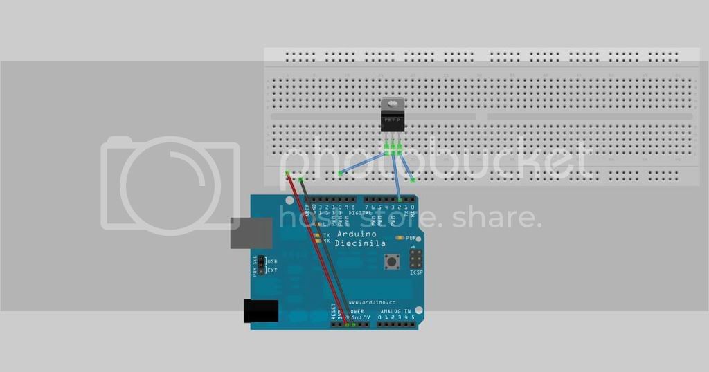
I'll try to do a simple schematic. But basically the setup is Arduino_5V -> sensor side leg. (Other) side leg -> ground. Middle leg -> Arduino pin. It's essentially the same as the ReadingRPM wiring, but without the LED.
I'm also struggling here slightly with the difference between unipolar, bipolar, latched, latching sensors...
To post a picture, if you don't have your own web server (come on, doesn't everyone?)... visit a free photo-hosting service like http://www.photobucket.com/ or imageshack or such. Once you upload your image there, then they'll give you a URL to your picture, and you can put that URL here.
Photobucket also makes it easy to get an "IMG Code" directly for forums like this. All that code is, is your picture URL wrapped in tags for the forum to recognize.
I looked at them and could not see any longer leg, or any sort of distinguishing characteristic
I know I struggled to find it on the data sheet, it is in the lower corner of the last page.
You don't need any resistors with the type of sensor you have.
If you wired them wrong then you probably have blown them because there is an IC inside as well as the sensor. it's probably an amplifier because these sensors have a very small output.
Unipolar - will only respond to one magnetic polarity
Bipolar - will respond to both magnetic polarities
Latched - will switch and hold that output state even when the magnet is removed until triggered again (possibly with the reverse magnetic polarity)
Thom,
It's not the middle connector that is the sensor output it's the one at the end. Also I don't think the strip board connects up the way you assume here. But as I never use the stuff I don't know.
As you might read in another current post this is something else I find a bit wimpy.
So - I probably don't need a latched sensor (all of the ones I have are latched!) as I only want it to be triggered instantaneously as the magnet passes the sensor, right? But if it's a bipolar latched, and the magnet passes perpendicular to the sensor, will that quickly latch and unlatch the sensor?
If I've blown them, that's not too much of a problem (I ordered two of each, just in case - better safe than sorry ), I shall try again. What a stupid mistake for me to make, I just assumed that the 3-leg setup was similar to that of a potentiometer.
I'll go and take a proper look at the data sheet now and see if I can work out which way the thing is supposed to go in.
As for the wiring on the bread board, I'm pretty sure it's correct. The two bottom lines are connected horizontally, and the dots in the middle are connected vertically, no? So by connecting 5V/Gnd to the bottom two lines, you create a 'bus' to which you can connect the rest of the components? I think this is correct as I've had servos, LCD, distance sensor working correctly with this setup.
I've go and have another tinker with this now, and see what happens.
Many thanks again, it really is appreciated. I'm used to posting as a knowledgeable linux user so it's nice to be helped and not flamed as an electronics n00b, hehe.
Right, I'll get on with this and post back in a bit.
Mike, thankyou, thankyou, thankyou! I've spent a ridiculous amount of time sweating over this, and the entire problem was due to my own silly assumptions and not paying attention to the data sheet!
I've rearranged the circuit to have the end leg as the control pin and hey presto, it worked immediately! I do have a bit of an issue with the fact it's a latched sensor, but that's easy to sort out with a bit of code or most likely a new sensor.
I've learned a valuable lesson here that I really should have been able to bring over from my coding experience - don't assume anything!
Should be able to get this thing working within the next couple of days now
Thanks a lot to everyone who contributed, it's been a brilliant help and saved me a lot of headache in the future, I think. No doubt I'll be posting some more queries soon.