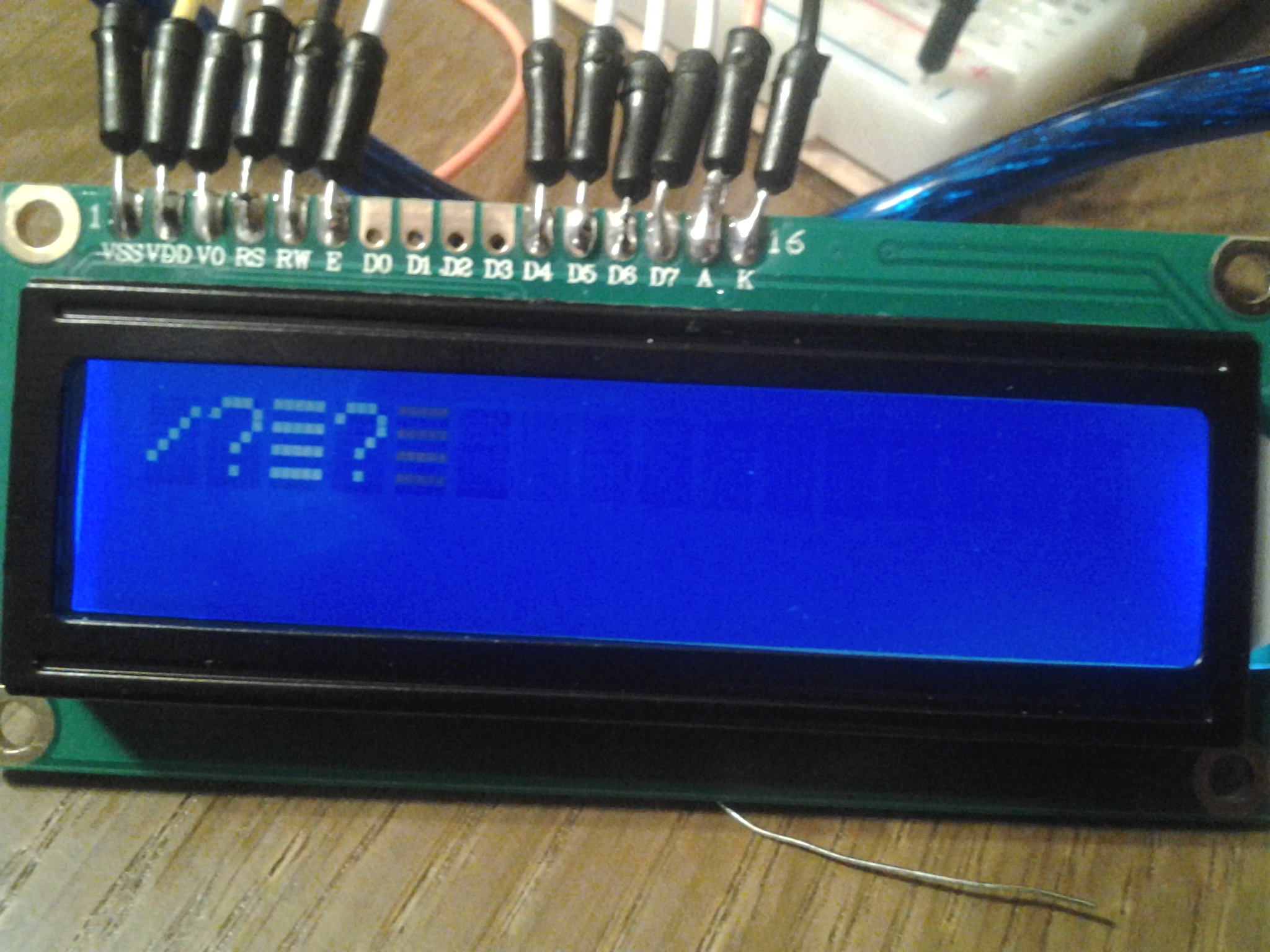
I have managed to successfully connect a Powertip PC1602F using the code and instructions from http://arduino.cc/en/Tutorial/LiquidCrystal, however when testing another 1602A from eBay using the same code I came to this problem. Instead of hello world I get strange question marks and arrows that change accordingly each second, I have checked the connections multiple times but with no success. What might be the problem ?
Well, looking at your display it looks bog standard. Have you tried re heating your joints to remove the possibility of a dry joint or possible checking for a break in one of the data wires? (all the others seem to work).
Can't see that photo, link seems to be broken.
If this (click ! ) is your first display, you can see that it is not standard (upside down, and numbered from right to left).
So if you have wired the new one the same, you're in for a surprise.
Sure, you still need to check your wiring, just to be sure.
The pins on the POWERTIP are not standard I know, but on the new one they are standard same as in the LCD tutorial. I will re-weld the data pins and see.
The photo is a public link on dropbox, it says it allowed for anybody with the link don't know what might be the trick.
The pins on the POWERTIP are not standard I know, but on the new one they are standard same as in the LCD tutorial. I will re-weld the data pins and see.
Just to clarify things a bit...
It is the pin locations that are not standard on the POWERTIP, the pin pin numbers and pin names do follow the (unofficial) standard.
If you follow a 'wiring diagram' such as the one in the Arduino LiquidCrystal tutorial then devices with the pins in the upper left will work and most with pins in the lower left will not.
If you follow a true 'schematic diagram' (not the abortions created by Eagle) then either type of display will work since a true schematic does not strive to have the pins shown in their physical locations. The pins are instead placed to make the signal flow as straightforward as possible.
Just a hint in translation - this is a common mistake which appears only too frequently on the Internet, particularly bad in Chinese references which indicates they have simply no idea of the actual subject.
It has been said before on this board:
In more than 1 language, there is no difference between welding and soldering (meaning in that language they are using the same word for both).
I'm assuming that is correct, because i don't know it isn't.
If so, this makes translating it to English a lot harder for those people.
MAS3:
It has been said before on this board:
In more than 1 language, there is no difference between welding and soldering (meaning in that language they are using the same word for both).
Two things here. I am not criticising ttt4x by any means whatsoever, but explaining something important that has the potential to make their communications in English, incomprehensible. Sure, we know what they mean in this case, but if he was talking to someone in another situation, the transaction could become completely confused.
My question then - in your language, are the two adequately distinguished? I'll bet they are. There really is no question that the processes are quite distinct. And I didn't go on to mention brazing.
MAS3:
I'm assuming that is correct, because i don't know it isn't. If so, this makes translating it to English a lot harder for those people.
The real problem is usually that at some stage someone who has no idea of the technical aspects involved, has attempted a translation of something they found or heard about and consulted some sort of translation dictionary - such as on the Internet - and accepted the incorrect translation, which has then been copied mindlessly as so clearly happens on eBay. It's essentially a sort of "Chinglish". Actual engineers of any sort in the respective country surely would discriminate correctly and know the different correct words, with a fair chance of understanding them in English as well. But a hobbyist just as likely would not, and may pick up the wrong terms from the ignorant marketers on eBay.
As I said, no slur on ttt4x's competence, but he really needs to know (and use) the correct term.
Any technically inclined native English speaking person who is frequenting an international forum should have no problem correctly interpreting 'welding' as 'soldering'.
Paul__B:
My question then - in your language, are the two adequately distinguished? I'll bet they are.
Got to answer that of course.
Soldering translates to Dutch as "solderen"
Welding translates as "lassen".
But that last word, lassen, can be different things too.
They all have to do with bonding or connecting however.
First thing that comes to mind, is twisting installation wires together using a plastic cover, like these:
Is called lassen in Dutch, but it isn't welding.
I understand you were trying to convey and explain the difference.
The "no idea" part was what triggered me to reply to it.
I don't believe that this is about someone not knowing what he was talking about, just someone who has no idea about the differences in other languages.
Back on topic:
Today i can see the picture.
The wires are the well known jumper wires, they are also well known to have bad connections now and then.
Those wires are not meant to be soldered, and i'd not be surprised if that would be the cause of your problems.
Also crossing wires is more likely to happen if you are using the same colors and it seems to me that you did do that.
I'd use as much different colors as possible, but keep red for power supply and black for GND.
MAS3:
I don't believe that this is about someone not knowing what he was talking about, just someone who has no idea about the differences in other languages.
But that is my point - I am quite sure it is about someone not knowing what he was talking about, but absolutely not the OP.
The problem - it seems to me - is that these Chinese purveyors of junk as widely disparate as Arduinos and dildoes from the same shop, clearly know nothing about electronics, but that others like our OP with less-than-perfect command of English despite their technical competence are subtly led to copy the perverse use of language and need to be corrected lest they spread the same errors virally.
Had the same problem. Floating ground due to following instructions too close .
Backlight requires +5v on A through a 220 ohm resistor and Gnd on K.
VDD requires +5V
VSS requires GND (Same ground as K) Don't just home run K to pin GND on Arduino. Send it to the minus rail of the proto board and connect both k and vss to the minus rail so they have a common ground.
VSS requires GND (Same ground as K) Don't just home run K to pin GND on Arduino. Send it to the minus rail of the proto board and connect both k and vss to the minus rail so they have a common ground.
This is not really correct.
The LCD controller interface is comprised of pins 1 - 14 of which 1 and 2 are the power connections.
The backlight interface is comprised of pins 15 and 16.
The two systems are completely independent and there is absolutely no need for a common ground.
Backlight requires +5v on A through a 220 ohm resistor and Gnd on K.
You may or may not need an external resistor but if you do it can be in either lead. In other words you could have the backlight cathode (K) above GND potential by virtue of having the resistor in that lead and the system would still function properly.
floresta:
You may or may not need an external resistor ...
It is rare that you do, particularly with those displays sold in quantity on eBay and other places. It would only be some oddball "surplus" items that are the exception.
This can be verified by locating resistor R8 on the board (or possibly R9), marked "101" or 100 Ohm. If this is present, no other resistor is required unless you wish to dim the display.