Analog switch IC behavior

My welder uses continuity between two pins in the remote plug to detect whether or not it should let the remote control the output, or whether it should let the dial on the front of the panel control the output. In the foot pedal supplied by the manufacturer, these pins are jumpered together so that plugging in the foot pedal immediately turns control over to the pedal, and un-plugging the foot pedal turns control back over to the front panel.

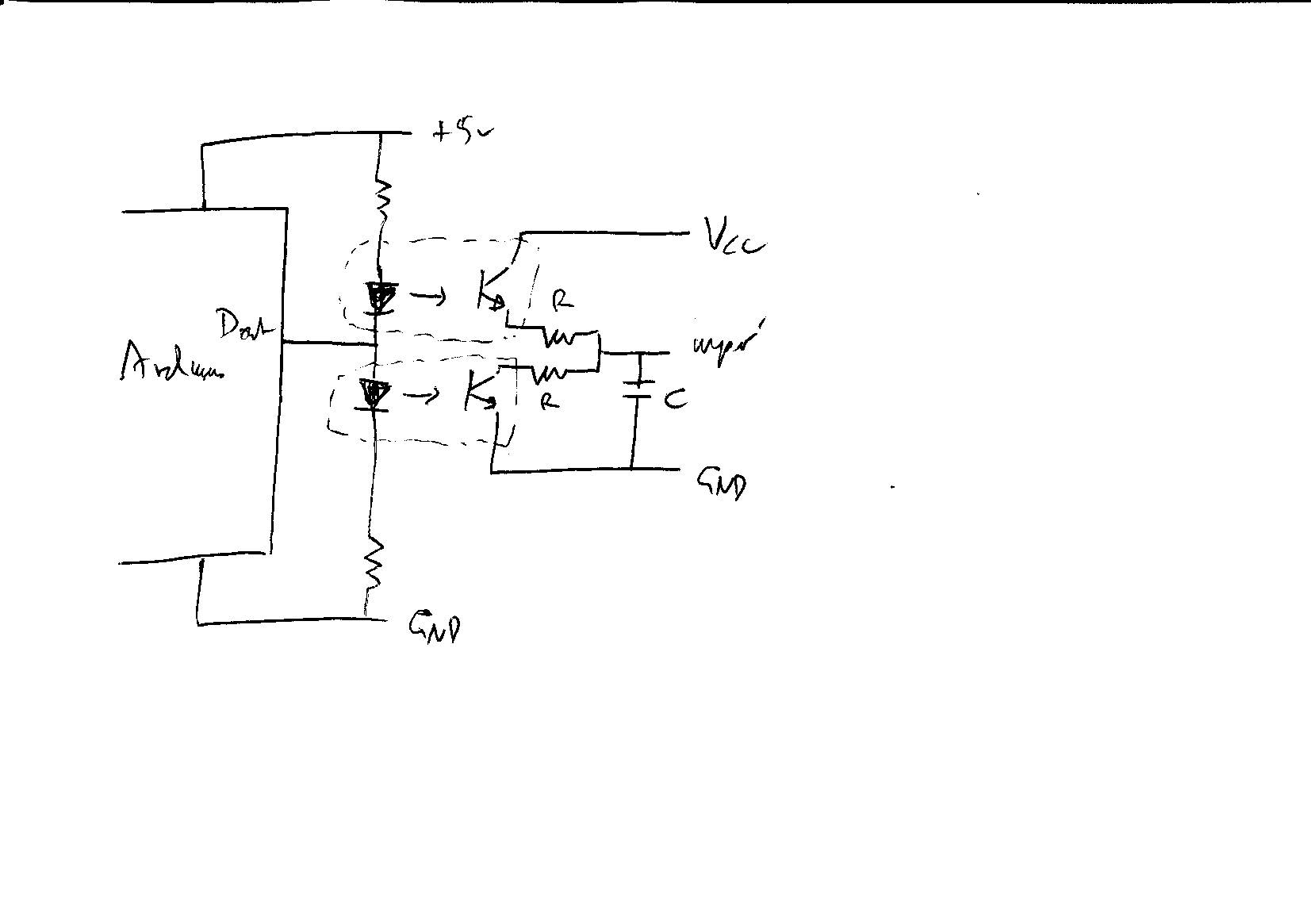
Instead of jumping these pins, I have pulled them back to my board so that I can pass control back and forth between my device and the front panel without having to un-plug the connector. I considered using several different components to switch this connection, including a MOSFET, an opto-isolated solid-state relay, and a 4066 analog switch IC. I am currently using the 4066, because 1) I accidentally ordered a power MOSFET with a 10-volt activation threshold, and 2) my relays are NC, and I need NO, because I want the contacts to be open when the Arduino is powered down so that the front panel has control in that state.

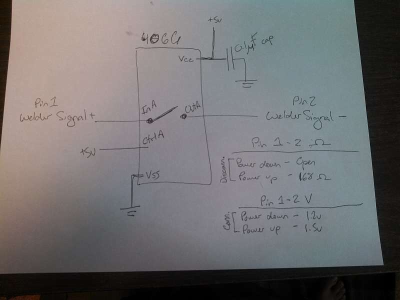
The 4066 appears to fit the bill. Between pins AIN and AOUT, there is no continuity when the chip is powered down, and there is about 168 ohms when the chip is powered up. Attached is a schematic of my circuit. You will see that I have bridged the control pin directly to the Arduino's 5v supply so that whenever the Arduino powers up, the switch should close. And readings with a multimeter confirm that this is working.

However, the results are not as I would expect. Whenever I plug the board into the welder, the welder acts as though there is continuity between the pins and disables the front-panel controls. This is even with the Arduino powered down, when no continuity should exist. Additionally, if I pull the 4066 from its socket, then the welder detects open between the pins and the front panel controls work. So there must be some signal path between pins 1 and 2 when the 4066 is plugged in, but I can't for the life of me imagine what it could be. Suffice it to say that things work fine if I install a manually-operated NO switch between the two pins of the welder's receptacle.

I have ordered some optically-isolated NO solid-state relays, which really should work, but I would like to have a better understanding of what is happening in this situation. I realize that not knowing what exactly is happening inside the welder is a bit of an impediment, but maybe some insight could be gleaned anyway.

I should mention that I am using two inputs on the 4066, but the other two are floating right now, in case that matters. Also, I have not tied the switch-detect circuit to the Arduino's ground, but there is another, parallel circuit that is used to detect the pedal position, and that one is tied to the Arduino's ground. The pedal-detect circuit is not running through the 4066. Not sure if that matters.

Could you show us the entire pin out of the chip?
(how its currently wired)

Here's the pinout of the 4066. Note that I have not yet hooked up control line B, because I haven't finished wiring up the board yet. Control lines C and D, and in/out C and D are not currently used in the project. Pins labeled "WPinX" indicate that they are connected to Pin X in the welder's remote socket. Pins 1/2 of the remote socket are used to detect the presence of the remote device. Pins 6/7 are used to indicate that the torch switch has been pressed and an arc should be initiated.

The 4066, like all other analogue switches does have some leakage and it looks like that is what is triggering your system. I would try putting a pull down resistor on the output side of this switch to short out any leakage. Something between 1K and 10K should be good enough if that is indeed the problem.

Note that I have not yet hooked up control line B, because I haven't finished wiring up the board yet. Control lines C and D, and in/out C and D are not currently used in the project.

You can't leave the inputs floating, you have to connect them to ground if there is no other form of input.

Grumpy_Mike:
I would try putting a pull down resistor on the output side of this switch to short out any leakage. Something between 1K and 10K should be good enough if that is indeed the problem.

So (and pardon my ignorance) a 1k-10k resistor, between the negative side of the circuit and the ground bus. Is that right? This will pull any leakage to ground without letting it "slip through" and be detected by the welder.

You can't leave the inputs floating, you have to connect them to ground if there is no other form of input.

Here, you're talking about the 4066's control inputs, right? Those I can easily just jump to ground.

Thanks.

between the negative side of the circuit and the ground bus.

Yes the pin 2 of the welder signal and ground. I assume you also have the ground of your welder connected to the ground of the arduino, if not you need to do that as well.

Here, you're talking about the 4066's control inputs, right?

Right.

Grumpy_Mike:
Yes the pin 2 of the welder signal and ground. I assume you also have the ground of your welder connected to the ground of the arduino, if not you need to do that as well.

Yes--or at least, I have tried to do that. The welder uses three pins to detect pedal position via a potentiometer (which I am replacing with the Arduino). The pins are +, wiper, and - (obviously). I have tied the - pin to the Arduino's ground, and I expect that this will have tied to two devices' ground to each other, but I can't be 100% sure about this, since I don't know what-all is happening inside the welder.

I suppose I could check for voltage between the pin 2 (the - pin of the "detect" circuit) and pin 3 (the - pin of the pot circuit).

If I was to use an opto-isolated, solid state relay, would these issues be circumvented?

I suppose I could check for voltage between the pin 2 (the - pin of the "detect" circuit) and pin 3 (the - pin of the pot circuit).

There is about 70 mV between these pins (and, therefore, between pin 2 and the Arduino's ground bus), so I think this means that pin 3 is an acceptable source of ground reference for the pin 1/2 circuit.

If I was to use an opto-isolated, solid state relay, would these issues be circumvented?

Could be but you would have to know about the welder circuit to be sure.
See how it goes with the pull down.

I would choose either a normally-open reed relay or an opto isolator for that application. The reed relay is simpler because it is polarity-independent.

I tried putting pulldown resistors on both of the switch connections (pin 1/2 and pin 6/7) going to the welder. No change in behavior. Additionally, with the analog switch IC plugged in, the "manipulate the welder's output" function doesn't work.

To elaborate, the welder's jack has seven pins, as follows:

1 - Pedal detect -
2 - Pedal detect +
3 - Pedal position (potentiometer) Vss
4 - Pedal position (potentiometer) wiper
5 - Pedal position (potentiometer) Vcc
6 - Torch switch -
7 - Torch switch +

Pins 1/2 and 6/7 are run into the analog switch IC. Pin 3 is connected to the Arduino's ground bus. Pin 4 is connected to a digital output pin that is putting out a voltage between 0 and pin-5 Vcc. Pin 5 is disconnected. The idea is to emulate the effect of the potentiometer by changing the voltage that the welder sees on pin 4. (For those who are going to now say, "Why don't you use a digital potentiometer?" let's just say that's another story, and I've been down that road six ways to Sunday. So far, this is the best option.)

When the analog switch IC is removed, manipulating the welder's output works correctly. When the analog switch IC is plugged in, the welder's output range changes from 0-96 amps to something like 30-60 amps. In other words, the voltage between pins 3 and 4 is changing from 0-2.7 volts to some other narrower-ranged value when the analog switch IC is plugged in.

Mind you, this is with the pulldown resistors installed.

The only way in which the analog switch IC or welder pins 1/2, 6/7 could be affecting the "welder output level" logic (pins 3/4) is via the ground bus, which leads me to believe that something more than just analog switch leakage is occurring.

Pin 4 is connected to a digital output pin that is putting out a voltage between 0 and pin-5 Vcc

I assume that is with PWM. You can not get that directly, you will have to filter the PWM first. PWM is a digital signal that goes from 0 to 5V all the time. The analogue write just controls the ratio of high to low.

As to the two other switches then an opto isolator with FET output stage looks like what is needed either that or a reed relay.

Hi, having had experience with repairs to welders of various types.
I would suggest that all lines that you want to cut and insert a switch of some sort, or switches you want to parallel you do with a relay.
Any series switching resistance means you are open to noise being included on the switched signal, and a welder of any sort has a lot of noise.
This ensures no worries low resistance connection and isolation between controller and machine and no ground reference problems.
I gather these connections are low voltage low current so small a number of relays built on an interface board would do the job.

I understand that you want to control the wiper input to the welder, have you found the ground of the welder control board that you are trying to control.
What is the voltage on Pin 3 and Pin 5 with respect to the welder ground? This very important.
As Grumpy_Mike says, you will have to filter the PWM output to get a smooth DC voltage that is the same as what is supplied by the potentiometer.
But you must find the welder controller ground first because the arduino cannot be isolated from it if you can get the analogue control to work.
Tom. 8)

Grumpy_Mike:
I assume that is with PWM. You can not get that directly, you will have to filter the PWM first. PWM is a digital signal that goes from 0 to 5V all the time. The analogue write just controls the ratio of high to low.

It is, and although this was a concern of mine, it appears to work flawlessly. You can see an example here:

I originally intended to filter the output with a capacitor, but I lack the basic knowledge to design a network to filter the output correctly, so I just plugged it up and gave it a try. I'm still a little suspicious of feeding a PWM signal into an input that isn't expecting it. My preferred approach would be to use a digital pot, but (long story short) I can't find a digital pot that meets the requirements of this application. (If you are interested in reading more about why I can't find a digital pot that works, there is a thread here: http://forums.adafruit.com/viewtopic.php?f=25&t=43053) There are various other approaches that I've tried, and some others that could work that I haven't tried, but as long as the PWM appears to be working, I've decided to put my effort towards other parts of the project.

I haven't actually welded with the Arduino controlling the output yet, so it's still possible that the display is showing an "averaged" output value, but the actual output is swinging high/low in sync with the PWM. I think this is unlikely, though, because I used to feed 0 to 2.7 volts PWM into the welder, and it showed the correct output value on the screen. Then I switched to feeding 0 to 5 volts PWM through a voltage divider (pulling max output down to 2.7), and the same output value was shown. If the welder was tracking the actual voltage (vs. the averaged PWM voltage), I would expect to see a different output on the display between these scenarios, since in one case the actual voltage was swinging to 5v, and in the other it was swinging to a true 2.7v. Nevertheless, the final test will be actually welding with the unit.

TomGeorge:
I would suggest that all lines that you want to cut and insert a switch of some sort, or switches you want to parallel you do with a relay.
Any series switching resistance means you are open to noise being included on the switched signal, and a welder of any sort has a lot of noise.
This ensures no worries low resistance connection and isolation between controller and machine and no ground reference problems.
I gather these connections are low voltage low current so small a number of relays built on an interface board would do the job.

I 100% agree with you. Going into this project, I was a bit confused as to why one would choose a relay vs. an analog switch IC vs. a transistor for signal-level switching, but I am quickly coming to see the deficits in switches that are not galvanically isolated from the controlled circuit.

I understand that you want to control the wiper input to the welder, have you found the ground of the welder control board that you are trying to control.

What is the voltage on Pin 3 and Pin 5 with respect to the welder ground? This very important.

That is a good question. I am taking ground from pin 3 of the connection, which is the negative leg of the pot circuit. I originally did that because the voltage difference between pin 3 and pin 4 is what controls the output of the welder, so it was necessary to match pin 3 to the Arduino's ground so as to allow the Arduino's PWM output to range from 0-max volts relative to the welder's 0-volt reference. Whether the welder's 0-volt reference for pin 3 is the same as the general ground for the welder is something that I don't know, nor do I know how I would determine that.

You know, I do have a thought: the welder has a ground lug on the back of it, for use in case the welder's high-frequency output is causing interference with electronic devices. Sort of, by definition, this lug should be the same as the welder's ground, shouldn't it? I could easily take a voltage reading between the grounding lug and pin 3.

As Grumpy_Mike says, you will have to filter the PWM output to get a smooth DC voltage that is the same as what is supplied by the potentiometer.

It'd be rude to ask you to do my homework for me, and I wouldn't learn anything, so instead, can you maybe point me to a reference to begin learning how to build a filter circuit to do this? I assume it'll involve capacitors? That's about the level of knowledge I'm starting with.

PS: I played around with a circuit simulator, feeding a PWM signal through a capacitor, and part of the challenge was that a circuit that stabilized within a relatively narrow voltage range took a long time to respond to changes in PWM duty cycle, and responsive circuits had too much variation in their output. The welder's output range is between 0 and 160 amps, so ideally, a circuit would have 2.7v / 160 discrete steps = 16 mV / step, in order to achieve 1-amp output resolution. Designing a circuit with such resolution, and with sufficient responsiveness for welding, is totally beyond my current abilities.

Thanks much for your input.

I measured voltage between the welder's ground lug and the grounding pin of the power plug, and as expected, it was 0v. I measured voltage between pin 3 of the remote connector and the ground lug and got no consistent voltage value. The multimeter just flopped around in the sub-100 mV range as if it was hunting for a reading.

... still thinking about this: what if I was to install an optically-isolated relay between the Vcc and the wiper pin of the potentiometer circuit, then feed the relay with a PWM signal to modulate the amount of voltage that was seen on the wiper pin? In this case, it seems like I would dodge any issues with matching the ground of the Arduino with the ground of the welder, although any potential issues with PWM signal would remain. This assumes that the relay has fast enough switching speed to keep up with the PWM signal. IIRC, the Uno's PWM frequency is something like 500 Hz, so that's a 1 kHz signal, or sub-ms switch time. A relay like the CPC1219Y has a listed max switch time of 5 ms, but the detailed charts show a more typical time of around 0.5 ms, with outliers around 0.7 ms, so perhaps it could work.

joshuabardwell:
... still thinking about this: what if I was to install an optically-isolated relay between the Vcc and the wiper pin of the potentiometer circuit, then feed the relay with a PWM signal to modulate the amount of voltage that was seen on the wiper pin? In this case, it seems like I would dodge any issues with matching the ground of the Arduino with the ground of the welder, although any potential issues with PWM signal would remain. This assumes that the relay has fast enough switching speed to keep up with the PWM signal. IIRC, the Uno's PWM frequency is something like 500 Hz, so that's a 1 kHz signal, or sub-ms switch time. A relay like the CPC1219Y has a listed max switch time of 5 ms, but the detailed charts show a more typical time of around 0.5 ms, with outliers around 0.7 ms, so perhaps it could work.

I suggest two opto isolators (or one dual opto isolator) configured as in the attached schematic. Choose R to be about half the value of the recommended potentiometer, and the product R * C to be about 0.1 to 0.2 seconds.

For the switches, use either opto isolators (if you can find a polarity that works), or reed relays.