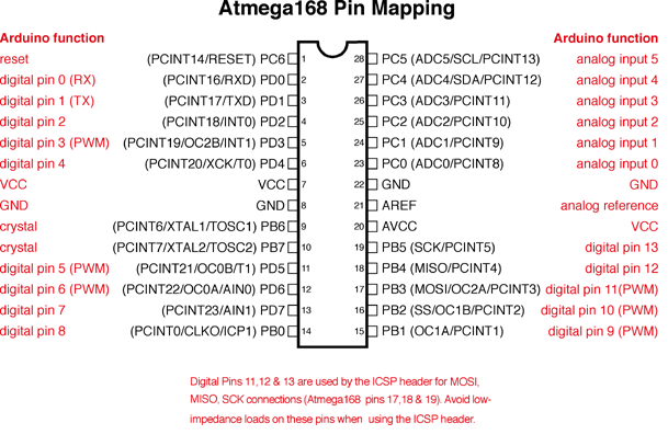
That is an extremely useful little .jpg there. I was looking at the schematic and thinking "pin 9" in the code referred to the the ninth pin down the left side to begin with. Then I found the pin map http://arduino.cc/en/uploads/Hacking/Atmega168PinMap2.png and thought that the IDE was doing something in compiling the code so that the signal went to the 14th pin of the controller. So following this tutorial http://arduino.cc/en/uploads/Hacking/Atmega168PinMap2.png I connect the yellow lead from my servo to the 14th pin on my Atmega328 (which is the only pin putting out any kind of signal) and it should work right?
Looking at the .jpg you provided, how would I know which 9 the code would output on?