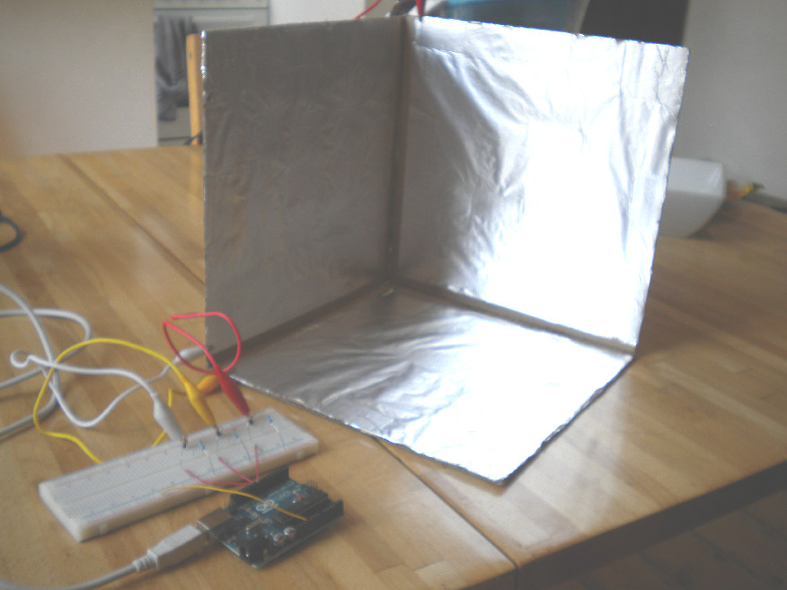
I have built a capacitive 3D controller to control a musical setup as shown in Kyle McDonald Instructable's article (read it here). I have made plates with sides of 25 cm. The article provides a circuit diagram as well as an Arduino sketch.
Basically it's functioning but I'd like to improve the setup but my knowledge in electronics is quite limited so any help would be appreciated.
First, the author uses shielded cables but I suspect it doesn't have any effect (the shield doesn't seem to be connected anywhere by the way). am I right ? What kind of circuit can really reduce the capacitive effect of the cable while preserving the one created by the plates and the hand ?
Second, the author writes it is possible to make the circuit more reactive by replacing the 270 kohms resistors with other values. Which ones would you use ? Moreover, the sketch samples sends the data only ten times per second. I'd like to reach a rate at least ten times higher. Is it possible ? How ?
Third, in order to avoid short-circuit with the hand, I'd like to cover the aluminum foils with a non-conductive material. What solution would you recommend ?
Fourth, I am not sure the signals coming to the card have the best possible range before being digitized. In the 25 cm range I have sometimes no more than 8 steps (so it's equivalent to a 3-bits resolution). How can I improve this ?
My guess Is that unshielded cables will become part of the sensor too, making it harder to get an accurate reading. But you could always try and see what happens.
Covering the aluminium foil probably can be done with all kinds of materials, plastic, wood, paper, cardboard or maybe a layer of paint.
Unfortunately I know too little to say much about the other 2 questions.
Thanks Simpson_Jr. I don't deny shielding can improve immunity to RFI but will the capacitive effect of the cable be reduced that way ? I guess it won't because it doesn't come from outside, right ?
What kind of circuit can really reduce the capacitive effect of the cable while preserving the one created by the plates and the hand
No kind of circuit.
Just good stable layout of the wiring between sensor and measurement circuit. Normally these need to be PCB wiring for stability.
I am not sure the signals coming to the card have the best possible range before being digitized. In the 25 cm range I have sometimes no more than 8 steps (so it's equivalent to a 3-bits resolution). How can I improve this ?
This is a weak demo of a weak effect, it is not very sensitive or reliable. They are not signals they are small changes in capacitance. If it were easy to improve do you not think someone would have done it by now. Capacitive sensors and switching are a big business and can be very sensitive but not with passive systems like this. There are many chips on the market that exploit this effect but most are active, that is they inject a signal and use that to measure the capacitance of the sensor.
I'd like to cover the aluminum foils with a non-conductive material.
Spray varnish.
Second, the author writes it is possible to make the circuit more reactive by replacing the 270 kohms resistors with other values.
I don't know what he means by reactive. But if you want to try then go up or down in standard steps and see if it improves. Down fro this would be 240K and up would be 330K. I suspect it makes little difference.
To me, "reactive" means "ability to track fast moves".
Well, reducing the values further would be a problem I guess.
There are many chips on the market that exploit this effect but most are active, that is they inject a signal and use that to measure the capacitance of the sensor.
Maybe I'd better go that way. Do you have any chip or circuit reference, Grumpy_Mike ?
Interesting list. However most of those chips seem to be made for touch or near proximity. Also, one interesting feature of the FreeScale ICs is the pin to shield the cables coming from the sensors.
I must say I am a bit frightened to use such chips because I have not conceived any circuit outside of a breadboard yet. Soldering an IC alone seems like a nightmare to me.
Don't worry about soldering, its no rocket science
Use a small tipped ,CLEAN, solder iron at about 3/4 of its max temperature (if you can adjust it).
FIRST make contact with the pin and pcb eye you want to solder, and then after about 1 second, just dib your solder (fine solder with flux soul) shortly to the area where pin and pcb eye are closest to each other. It should liquify nearly instantly, so remove your solder iron tip at once.
You should try a bit to find out the right amount of solder you should use for best results. Generally I like to use as little as possible, so you will not build up tear like solder shapes.
Do not heat pins or solder longer than necessary, it might damage your hardware or generates "cold" solder conections.
The PSoC micro controller Cypress PSoC - Wikipedia has built in analogue blocks that can easily be configured as a touch sensor. Touch sensors and what you are trying to do are one and the same thing so don't get confused. The touch sensor just makes a decision when the signal has reached a certain point to say "touched" but the continuously monitored signal is exactly what you are after.
There are development kits available.
There might be an important difference between a touch sensor and a distance sensor: a touch sensor is intended for very short distances (< 1 cm) while the distance sensor might deal with much greater distances (up to 50 cm in my project). Therefore I suppose there might be a sensitivity difference. Also, with a touch sensor the circuit is usually close to the electrodes while in my project the distance might be bigger. In this regard, the Freescale MC33794 and MC33941 get the point because they include a pin to shield the cables going to the electrodes. However these chips are now considered as obsolete and become hard to find (they were developed for the automotive market at first, and it seems this industry uses other types of sensors nowadays).
The Cypress PSoC might be a solution but as I have just begun with Arduino I won't try another platform so quickly, also because I am a Mac user and it seems there's no PSoC SDK for this OS. Maybe I'll go with the AD7746, the breakout board from Sparkfun will save me from the soldering work...
I too am a Mac user, I find boot camp useful for these occasions.
Well, my hard disk is so completely full already that I deleted all the PowerPC parts of the applications to gain some space. Boot Camp will be for my next Mac.
I have just discovered the Si114x IR-sensing chip family from Silicon Labs. They claim that the 3-leds version can be used for (close) 3D position tracking. Have a look at that video. It features the evaluation board (SI1140DK) with 3 leds and X/Y/Z tracking. It's too bad that this board uses a C8051F800 MCU. If it came with an Atmel controller or as a breakout board I'd buy it immediately because it would ease the construction of a 3D interface quite a lot I guess.
The chip is ridiculously small (2 mm x 2 mm) and is sold only as a SMD component. Can a human being solder this ? I'd better find someone willing to make a breakout card for me...
