I apologize that this post is large, but I can't make it smaller and be able to articulate my application and question.
I have a custom circuit board I created that uses an Arduino Nano and Wiznet WIZ811MJ ethernet interface. The board controls a TTL critical time shuttering circuit of an LED board made up of discreet red, green and blue LED's. I use Timer1 pin 9 for the exposure integration control.
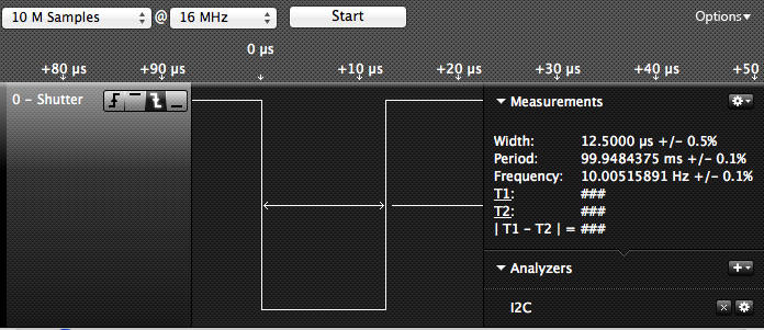
My code is derived from the "Timer1" example on the Arduino site. It puts Timer1 into "phase and frequency correct pwm" mode, which is how the Timer1 example worked. I don't need PWM, but if I disable it on the registers, the timer only turns the lamps on and they never turn off. I set the duty cycle to 3, which means that the pin goes low for 99.7% (the exposure period) of the pwm cycle and returns to high for 0.03%. If I set it lower than three, I cannot get exposures shorter than 1-5ms without the output sticking.
My application requires a single execution of the timer (LOW during shuttering,HIGH when off). Based on my limited understanding of the Atmel timer registers, it is unclear to me if I can program the registers into an alternate mode of operation to make the timer execute just one LOW/HIGH cycle and then go idle. Presently, I am turning the timer off in the ISR() software interrup routine, but it is causing problems for exposure times under 200 microseconds and is not very reliable. I'd like to be able to get down to just a few microseconds, if possible, and I must be able to generate thousands of continuous executions without any failure or incorrect exposure times, as this is a motion picture application.
I used to work with AMD 186 processors, which worked a little differently. They had separate interrupts for each side of the PWM, and you could more easily program them for a single execution.
Here is my code (most of which comes from Timer1 example):
Timer Functions:
void LED_V3::InitializeTimer()
{
	//Initialize Timer1
	TCCR1A = 0;                 // clear control register A
	TCCR1B = _BV(WGM13);        // set mode 8: phase and frequency correct pwm, stop the timer
	DDRB |= _BV(PORTB1);        // sets data direction register for pwm output pin
    TCCR1A |= _BV(COM1A1);     // activates the output pin
}

void LED_V3::SetTimerPeriod(long microseconds)
{
//	unsigned char		clockSelBits;
//	char				oldSReg;
//	unsigned int		pwPeriod;

	long cycles = (F_CPU / 2000000) * microseconds;                                // the counter runs backwards after TOP, interrupt is at BOTTOM so divide microseconds by 2
  if(cycles < RESOLUTION)              m_clockSelectBits = _BV(CS10);              // no prescale, full xtal
  else if((cycles >>= 3) < RESOLUTION) m_clockSelectBits = _BV(CS11);              // prescale by /8
  else if((cycles >>= 3) < RESOLUTION) m_clockSelectBits = _BV(CS11) | _BV(CS10);  // prescale by /64
  else if((cycles >>= 2) < RESOLUTION) m_clockSelectBits = _BV(CS12);              // prescale by /256
  else if((cycles >>= 2) < RESOLUTION) m_clockSelectBits = _BV(CS12) | _BV(CS10);  // prescale by /1024
  else        cycles = RESOLUTION - 1, m_clockSelectBits = _BV(CS12) | _BV(CS10);  // request was out of bounds, set as maximum

  m_oldSREG = SREG;
  cli();							// Disable interrupts for 16 bit register access
  ICR1 = m_pwmPeriod = cycles;                                          // ICR1 is TOP in p & f correct pwm mode
  SREG = m_oldSREG;

  TCCR1B &= ~(_BV(CS10) | _BV(CS11) | _BV(CS12));
}

void LED_V3::StartTimer()
{
	unsigned int tcnt1;

	do {	// Nothing -- wait until timer moved on from zero - otherwise get a phantom interrupt
	m_oldSREG = SREG;
	cli();
	tcnt1 = TCNT1;
	SREG = m_oldSREG;
  } while (tcnt1==0);


	TCCR1B |= m_clockSelectBits;

}
void LED_V3::SetTimerPWM(int duty)
{
	// expects duty cycle to be 10 bit (1024)/Output Pin Must Be 9

	unsigned long dutyCycle = m_pwmPeriod * duty;

	//Pin 9
    DDRB |= _BV(PORTB1);                                   // sets data direction register for pwm output pin
    TCCR1A |= _BV(COM1A1);                                 // activates the output pin


  dutyCycle *= duty;
  dutyCycle >>= 10;

 // Serial.println("LED_VE:SetTimerPWM()");
 // Serial.println(dutyCycle);

  m_oldSREG = SREG;
  cli();
  OCR1A = dutyCycle;	//Pin 9
  SREG = m_oldSREG;

  TCCR1B |= m_clockSelectBits;

}
void LED_V3::AttachTimerInterrupt(void (*isr)())
{
  isrCallback = isr;                                       // register the user's callback with the real ISR
  TIMSK1 = _BV(TOIE1);                                     // sets the timer overflow interrupt enable bit

  TCCR1B |= m_clockSelectBits;
}


Interrupt Function:

void StopExposure()
{
	TCCR1B &= ~(_BV(CS10) | _BV(CS11) | _BV(CS12));
	gBusy = 0;
}
This is my program setup code:
//Timer1 Initialization
	InitializeTimer();
	SetTimerPeriod(1000);
	SetTimerPWM(3);
	AttachTimerInterrupt(StopExposure);
Finally, these are the functions I call to set up an exposure:
SetTimerPeriod(m_exposureRed);
StartTimer();
I would appreciate any guidence as to to how it might be possible to automate a single exposure without having to kill the timer during the interrupt routine. I have read many of the Atmel docs and Arduino posts, but timer registers are still very confusing to me.
Thank you.