I've got a battery powered portable device and have a couple of queries about grounding.
There is a number of individual circuit boards within the housing, and I want an effective way to connect the grounds. I know it isn't ideal to have a heap of separate grounds interconnected with a mess of wires so I thought I'd ask what people here thought. I'm guessing providing I use relatively thick wires to connect them (and ensure the contacts are sound) to be best, and ensuring the ground pads of each individual circuit is reasonably large and separately spatially from any digital (or fast switching) lines. Is there any other tricks worth considering?
Also, is there any merit grounding the housing itself (or at least the metal parts of it, it is mostly made of hard plastic), or further, creating a metal shield within the housing? If a metal shield is present, is it worth ground this to the circuit too, or keep it isolated?
A simple rule is to select one board as the master ground (in this case the arduino) or 0v point. Then all other board grounds are connected to a single common point on this board via separate radial leads. The intent is to prevent current flow demand of individual boards affecting others as may happen if you used a single jumper wire to inter-link the boards together
Note that in portable devices the term "ground" is used in place of "common reference point" which may cause confusion since it may be inferred that a stake needs driving into the earth's crust - which is not necessary.
There may of course be differing opinions on the matter, but that's democracy for you.
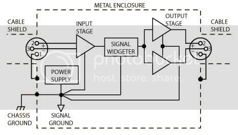
Here's a common arrangement. Note that the case is connected to the signal ground at only one point and the star arrangement of the signal ground ensures that no signal current flows through that connection. That's the ideal for balanced signals as in the figure. If the signals are unbalanced (the cable shields carrying signal current) then the situation is less ideal.
Note that in portable devices the term "ground" is used in place of "common reference point" which may cause confusion since it may be inferred that a stake needs driving into the earth's crust - which is not necessary.
And that my friend is the root of the problem and misunderstanding that many newcomers have when starting in electronics, and it's all our faults. We tend to overuse and misuse the term 'ground' when we really should call it circuit common or just common. The use of a circuit common is mostly a graphical aid to keep from having to draw all the circuit return paths to the voltage source in schematic drawings.
A true ground would be a connection that ends up at a ground rod somewhere which of course a battery powered circuit does not have or require (unless you are dealing with RF antenna circuits where you need a true ground for antenna efficiency). In fact any circuit that is powered from a transformer coupled power source (like a 'wall wart') does not require a true ground to operate, but might require it for electrical code requirements.
So most of us are guilty of 'overloading' the usage of the word 'ground', but it's so common (pun, yes?) in usage that nothing is bound to change or correct that usage.
So most of us are guilty of 'overloading' the usage of the word 'ground',
In the UK we have the term Earth for the stake in the ground and reserve ground, or circuit ground for the common signal point. It doesn't stop the confusion for beginners but at least we have a different word for it.