Here is a sketch I have cobbled together to create a "Hammond" sound synthesiser using an Arduino UNO.
It uses MIDI signals and an MCP4921 DAC to pick up the syntheised sound via SPI on a "shield". (I didn't know what a "shield" was until recently, but its a piggy-back PCB that picks up the Arduino pins and contains electronics as required for the project):
/* --------------------------------------------------
   Hammond organ set to 636554078
   --------------------------------------------------
*/
byte thisByte = 0; // Midi note byte read from serial port
bool note = true; // True if current byte is to be treated as a note, false otherwise
int notesHeld = 0; // The number of keys pressed & held
uint16_t saveNote = 1845; // Temporary storage for Note value
uint16_t sample = 0; // The amplitude for the note from the sine[ ] table
uint16_t incr = 0 ; // the oddly-named value for the extra amount to be added to get the required output frequency
uint16_t pos = 0; /* oscillator position */ /*(I copied this without knowing what it is for)*/

const uint8_t sine[] =
{
  229,  230,  232,  233,  235,  238,  241,  243,  246,  248,  250,  252,  253,    253,    254,
  254,  250,  248,  240,  235,  233,  230,  225,  220,  215,  206,  203,  201,  200,  197,  195,
  194,  195,  195,  196,  198,  200,  205,  210,  212,  214,  218,  220,  222,  223,  224,  225,
  225,  224,  222,  221,  218,  214,  202,  198,  194,  188,  186,  184,  182,  181,  180,  180,
  179,  179,  178,  177,  176,  175,  175,  175,  175,  174,  174,  173,  172,  170,  169,  168,
  166,  163,  159,  156,  149,  145,  135,  129,  124,  120,  115,  105,  88,   84,   78,   65,
  55,   48,   45,   42,   38,   36,   34,   33,   33,   32,   31,   31,   32,   33,   34,   35,
  36,   38,   40,   43,   46,   49,   51,   53,   55,   57,   59,   63,   66,   70,   75,   85,
  95,   108,  118,  128,  138,  148,  158,  165,  167,  170,  178,  182,  184,  185,  187,  189,
  190,  190,  190,  189,  189,  188,  185,  182,  180,  178,  176,  173,  171,  169,  168,  167,
  166,  166,  167,  168,  170,  175,  180,  185,  190,  195,  202,  204,  205,  206,  207,  206,
  205,  203,  201,  195,  190,  185,  183,  181,  179,  177,  175,  173,  171,  169,  167,  165,
  163,  161,  159,  157,  155,  154,  152,  151,  150,  150,  149,  147,  144,  141,  138,  135,
  132,  129,  126,  123,  121,  119,  117,  115,  113,  111,  109,  107,  105,  103,  102,  101,
  100,  100,  101,  102,  103,  104,  105,  107,  110,  115,  120,  130,  140,  145,  156,  160,
  164,  168,  172,  176,  180,  184,  188,  192,  196,  200,  204,  208,  212,  216,  220,  224,
  225,  227,  228,
}; // 256 values but NOT a sinewave, now re-populated for a Hammond sound

static const uint16_t midiNotes[] = // Values from MIDI 21 to 98
{ // i.e. 88 values
  0,                                      // Note OFF value
  115,
  122,
  129,
  137,
  145,
  154,
  163,
  173,
  183,
  194,
  206,
  218,
  231,
  244,
  259,
  274,
  291,
  308,
  326,
  346,
  366,
  388,
  411,
  435,
  461,
  489,
  518,
  549,
  581,
  616,
  652,
  691,
  732,
  776,
  822,
  871,
  923,
  978,
  1036,
  1097,
  1163,
  1232,
  1305,
  1383,
  1465,
  1552,
  1644,
  1742,
  1845,
  1955,
  2071,
  2195,
  2325,
  2463,
  2610,
  2765,
  2930,
  3104,
  3288,
  3484,
  3691,
  3910,
  4143,
  4389,
  4650,
  4927,
  5220,
  5530,
  5859,
  6207,
  6577,
  6968,
  7382,
  7821,
  8286,
  9301,
  9854,
  10440,
  11060,
  11718,
  12415,
  13153,
  13935,
  14764,
  15642,
  16572,
  17557,
  19989,
};

void setup()
{
  Serial.begin(31250);

  pinMode(7, OUTPUT); // connected to an LED on shield piggy-back board

  cli();
  TIMSK2 = (1 << OCIE2A); // Timer 2 interrupt at 15625Hz.
  OCR2A = 127; //  Set Output Compare Register = 127 to define the # of time intervals to be timed
  TCCR2A = 1 << WGM21 | 0 << WGM20; // See ATMEGA328P Page 150 for details
  TCCR2B = 0 << CS22 | 1 << CS21 | 0 << CS20;
  SPCR = 0x50; // Set SPI control register to binary 0101 0000; SPE and MSTR bits are set  HIGH
  SPSR = 0x01; // Set SPI status register to binary 0000 0001; SPI2X is set high here (SPI double speed)
  DDRB |= 0x2E; // 2E is 0010 1110 setting pins 9, 10, 11 & 13 to be outputs
  PORTB |= (1 << 2); // Left shift twice -> 0000 0100 and compound bitwise OR with whatever is already in PORTB
  // Looks like pin 10 is being set to a HIGH level, used as SS signal on my hardware

  sei();
}

ISR(TIMER2_COMPA_vect) {

  OCR2A = 127; // already done earlier . . .
  pos += incr; // Compound addition, add incr to pos, result in pos
  sample = sine[highByte(pos)] << 2; // Determines the output frequency depending on the Midi note sent in
  PORTB &= ~(1 << 2); // Toggle PORTB pin 10 LOW
  SPDR = highByte(sample) | 0x70; // 70 hex = 0111 0000; pick up the higher bits only
  while (!(SPSR & (1 << SPIF))); // Wait for SPIF going HIGH when serial transfer is complete, is SPI Interrupt Flag
  SPDR = lowByte(sample); // Pick up the lower 8 bits of the 16-bit byte in (sample)
  while (!(SPSR & (1 << SPIF)));
  PORTB |= (1 << 2); // Toggle PORTB pin 10 HIGH

} // End Timer Interrupt service routine

void loop()

/* Arrive with boolean "note" set to TRUE,
   notesHeld = 20 (arbitrary non-zero value, contains the current number of keys pressed simultaneously),
   thisByte = 0.
   Code is designed to allow a player to hear all the notes played as if the synth were polyphonic i.e.
   fills the gaps which would be left if the code responded to each zero velocity byte individually
   instead of waiting for the last key to be lifted */
{
  if (Serial.available() > 0)
  {
    thisByte = Serial.read(); // Read a Midi number byte from serial buffer

    if (thisByte == 144) // This is a new Note On situation
    {
      note = true; //  True if current byte is to be treated as a note, false otherwise e.g. for a velocity byte
      incr = 0; // Silence the synth
      notesHeld = 0; // 144 emans that all piano notes have been released
    }
    else
    {
      if (note) // It's a note, not a velocity
      {
        note = false; // Next byte HAS to be a velocity
        saveNote = thisByte; // Keep this note I.D. handy
      }
      else
      {
        if (thisByte == 0) // Must be a zero velocity byte
        {
          --notesHeld; // So decrement the number of notes currently held down
        }
        else
        {
          ++notesHeld; // Increment the number of notes currently held down
          incr = midiNotes[(saveNote - 20)]; // Subtract 20 for correct position in the note table
        }
        if (notesHeld == 0) // Now received a zero velocity byte for each note previously pressed
        {
          incr = 0; // Once the last note is released, turn off the tone.
        }
        note = !note; // Next byte HAS to be 144 (if using a Casio AP-21 piano anyway)
      } // End IF note
    } // End IF thisByte
  } // End serial.available
} // End Loop()

/*
      Some code I used during testing:
      Serial.print("  This byte:  "); Serial.print(thisByte);
      Serial.print(" Note true/false: "); Serial.println(note);
      Serial.print(" notesHeld:  "); Serial.print(notesHeld);
      digitalWrite(7, HIGH);
      delay(150);
      digitalWrite(7, LOW);
      delay(150);
      Serial.print("  This byte after if 144:  "); Serial.println(thisByte);
*/
I have ONLY tested it on an UNO and with a Casio AP-21 digital piano.
I note that the piano MIDI is of the "running" variety, where it doesn't send a Note ON message if a key is already held down. This necessitated a lot of the coding in the main Loop, because simply outputting each note caused the synthesiser to keep being silenced in a musically unwanted way.
Attached are details on the shield used.
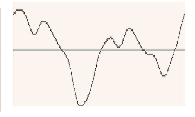
The wavetable was created by recording Middle "C" from a genuine 1960's tonewheel Hammond organ and manually digitising the 256 amplitude values needed for a single cycle of the waveform. I set the 9 drawbars to 636554078 because I liked the sound.
The code sets the sampling rate at 15kHz although this results in higher notes having poor quality. I might try doubling the sampling rate to see if this improves as in theory it should do. The 15kHz is grand for LF audio but the Hammond is able to put out high harmonics and these need to be clear so they don't mash up the sound.
Getting the wavetable followed these steps:
1: Record organ on (phone)
2: Input 1 -2 seconds into Reaper
3: Expand Reaper graphic and select one cycle of waveform
4: Copy & paste screenshot into Paint
5: Expand to A4 size (roughly)
6: Print
7: Over print the print with an Excel 255 x 255 grid
8: Type 256 values into an Excel wavetable file
9: Use Excel chart to ensure waveform is smooth, i.e. no discontinuities.
10: Copy wavetable data into sketch
11: Give it a lash


Hammond.ino (6.9 KB)