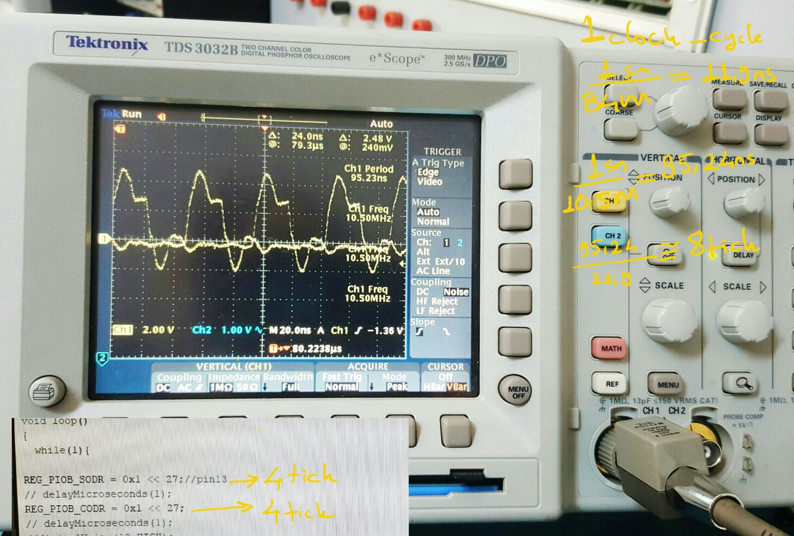
I have measured on off time of digital pin of due by using oscilloscope .
Later I have tested with number ticks.
first line of code 5 ticks others 2 ticks so I ignored first 5 ticks.
I have seen on oscilloscope screen and serial monitor different things.
Every for setting logic 1 and 0 frq=10.5Mhz which means 8 ticks.
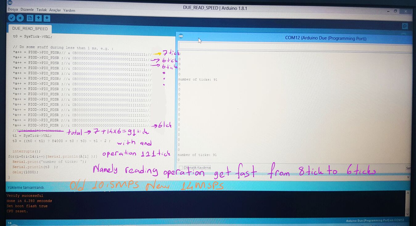
On serial monitor for setting logic 1 and 0 number of ticks=4 tick
Oscilloscope says every line of code takes 4ticks
Serial monitor says every line of code 2 ticks.
If I couldn't trust number ticks.
How do I measure frequency correctly ?
I am taking 8000 samples 888micro second.
Matlap calculate fft according to the 888 micro second for 8000 samples.
Below I added how I take 8000 samples.
void readValues() {
  EthernetClient client = server.available();
  byte X[8000];
  uint32_t i, t0, t1,t[8000];
  byte *a = &X[0];

  elapsed_Time = 0;
  noInterrupts();
  //PIO_PDSR&0B00000000000000000000000011111111  ARDUINO DUE  (MSB)D11 D14 D15 D25 D26 D27 D28 D29(LSB) PORTLARININ STATUS REGISTER

  t0 = SysTick->VAL; //

  // first reading  7clk laters 3clk

  T(T(T(*a++ = PIOD->PIO_PDSR & 0B00000000000000000000000011111111))) //1) 3008tick //with this method we can read port 1000 times with one line of code.
number of tick is same with write 1000 line of code from A[0] to A[1000]
  T(T(T(*a++ = PIOD->PIO_PDSR & 0B00000000000000000000000011111111))) //2) 3000tick
  T(T(T(*a++ = PIOD->PIO_PDSR & 0B00000000000000000000000011111111))) //3) 3000tick //PIO_PDSR= Pin Data Status Register
  T(T(T(*a++ = PIOD->PIO_PDSR & 0B00000000000000000000000011111111))) //4) 3000tick
  T(T(T(*a++ = PIOD->PIO_PDSR & 0B00000000000000000000000011111111))) //5) 3000tick
  T(T(T(*a++ = PIOD->PIO_PDSR & 0B00000000000000000000000011111111))) //6) 3000tick
  T(T(T(*a++ = PIOD->PIO_PDSR & 0B00000000000000000000000011111111))) //7) 3000tick
  T(T(T(*a++ = PIOD->PIO_PDSR & 0B00000000000000000000000011111111))) //8) 3000tick


  t1 = SysTick->VAL; //  to-t1=24008ticks
   interrupts();
    a=&X[0];//pointer goes to the beginning of array .
    T(T(T( client.write(*a++))))//1)
    T(T(T( client.write(*a++))))//2)
    T(T(T( client.write(*a++))))//3)
    T(T(T( client.write(*a++))))//4)
    T(T(T( client.write(*a++))))//5)
    T(T(T( client.write(*a++))))//6)
    T(T(T( client.write(*a++))))//7)
    T(T(T( client.write(*a++))))//8)


  Serial.print("n_ticks: ");
  Serial.println( ((t0 < t1) ? 84000 + t0 : t0) - t1 );
  Serial.println();

  delay(30);


}
and the most maddening thing is every reading of a port takes 8 ticks with sending its values to an array .
But reading a port takes 4 ticks for reading a port without sending array.
???
Before I asked for number of ticks But I couldn't find solutions in assembly language.
if solution is in assembly file.
if the problem have a solution in assambly
(Frankly I haven't experienced in assembly field.)
please send clearly understandable definition.
Yes You are right
one of my main problem was taking samples as soon as fast.
Uno reads 1600 times in 304micro seconds.
So I readed digital port of arduino uno at the speed of 5M samples per second and every reading 0.19 micro second which means nearly 3 clocks cycles.
while uno is able to reading a port in 3 clocks cycles why reading a port for due takes 8 clock cycles.
if I solve this problem my speed of samples per second will increases Then I can show on Matlab frequency via fft as correct as possible.
The short answer is that the flash memory and GPIO ports in the Due are not as much faster than the AVR as the CPU is. In fact, the flash memory is about the same speed (~50ns) as on an AVR (however, there are other factors that make it "effectively" faster.) It looks like PIO access takes at least two clocks (assuming that it is configured to be as fast as possible.)
Newer ARM Microcontrollers were more "aware" of engineers' desire to read/write GPIO as quickly as possible, and moved the GPIO controller to higher-speed bus interfaces, as well as making "flash acelleration" more complicated. For example, the SAMD21 on Arduino Zero actually has an instruction cache, AND has GPIO on a "low-latency CPU local bus", so it would be interesting to see if the Zero (48MHz) runs your code faster than a Due (84MHz.) I can't tell just from looking at the datasheet; ARMs are complex and have all sorts of features that interfere with figuring out execution speed just from looking at the code
Sam3x8e reads 32 input pins in 6 to 8 clock cycles. In your case, if I understand what your are actually doing, you need to read the first 8 input pins of PIOD.
8 input pins reading / 8 clock cycles should give you something close to 1 clock cycle for 1 input pin reading, right ?
PIOD->PIO_PDSR & 0B00000000000000000000000011111111
I have modified upper line to
PIOD->PIO_PDSR
So I have removed and& operation .
Result
Before with and operation every reading takes 8 clock cycles
After removing and operation it takes 6 clock cycles which means
Speed of reading increases from 10.5MSP to 14MPS.
it would be interesting to see if the Zero (48MHz) runs your code faster than a Due (84MHz.)
I think I've shown that the Zero will read or write a port at essentially once per clock cycle if you use the (relatively undocumented, even in the datasheet) IOBUS high speed access.
That means that a string of
    p->OUTTGL.reg = (1 << 21);
    x = p->IN.reg;   // x is volatile, so the store always happens
produces a ~5.3MHz square wave, which means that the sample/store is happening at better than 10MHz.
The instruction sequence produced is:
    2138:       61d9            str     r1, [r3, #28]  ;; do pin toggle
    213a:       6a18            ldr     r0, [r3, #32]  ;; load port value
    213c:       6010            str     r0, [r2, #0]   ;; store into RAM
Hi everybody
A colleague of mine advice me that
to detect elapsed time for any function in the codes
set a pin high start your reading process
end of reading set pin off
and measure the On time of the signal via oscilloscope.
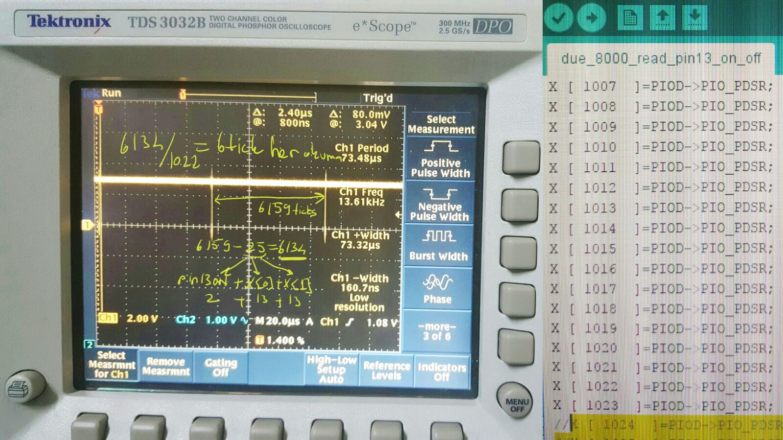
I have added the image of oscilloscope.
Setting-pin13-ON =2 ticks
Reading X [0] =13 ticks
Reading X [1]=10 ticks
Reading X [2]= 6 ticks
.
.
.
Reading [1023]=6 ticks
So I have seen 73.32ns on oscilloscope screen.
It's Ok to say after two reading Due reads port in 6 clock cycles .
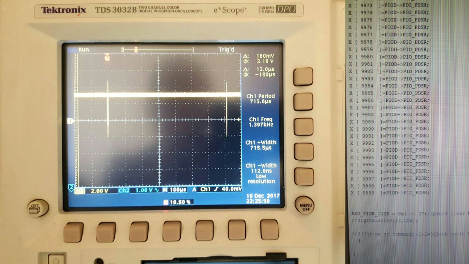
But When I tried to read 8000 times
Something went wrong. It takes to much time to finish reading.
I don't know why Due behave like that But of course there is an answer in depth of MCU structure.