What is the right way to use a pull up resistor?

or

I'm talking about the 100 Ohm resistor that is added in the first example. What is it's purpose?
What is the right way to use a pull up resistor?

or

I'm talking about the 100 Ohm resistor that is added in the first example. What is it's purpose?
It protects against a bad programming the pin as Output.
Can use the internal pullup instead:
pinMode (pinX, INPUT_PULLUP);
or
pinMode (pinX, INPUT);
digitalWrite (pinX, HIGH); // enables internal pullup
This keeps input pins from floating and providing nonsense readings.
100 ohm is way too low a value. Internal is 20K to 50K.
External only needs to be 10K.
100 ohm is way too low a value. Internal is 20K to 50K.
Agreed, this 100 Ohms before the pin is not a Pullup nor Pulldown resistance.
What is it's purpose?
If "none" is a too simplistic answer, there just remains (my previous reply) "to limit the current into the Arduino pin in case of errors".
Any other suggestions ?
Or to limit the current out of the pin. Suppose the pin were for some reason configured as an output and written to HIGH with the switch closed.
So if it's correct that it serves to protect the chip, shouldn't it be at least 125 Ohm? The atmega is rated up to 40mA @ 5V so 5/0.04 = 125 Ohm (150 Ohm to be shure)
It doesn't have to be there... unless you would like to save yourself from a stupid mistake on a breadboard where you would accidentally cause a short on the PIN and "smoke" it. I have seen designs with other non-Atmel microcontrollers where 200 Ohms is used. In this particular circuit... it's best suited for bread board usage... but when you move to a final PCB where stray wires are unlikely, you can remove it.
So, it's probably "what it is" for the following reasons:
100 Ohm resistor is readily available
100 Ohm resistor is "close enough"
Many "hobbyists" go on and on about how 40 Ma is just a "line in the sand" set by Atmel as a safety margin and the pin can tolerate 60mA or even 80mA with no ill effects (I'm not one of those) but this discussion continues "ad nauseum" in other threads and does not need to be continued here
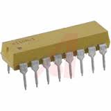
This is why I keep a few 220 Ohm DIP arrays in my "junkbox".

If you're trying to limit current flow in & out of the pin, you want the resistor in series with the pin, not pulling up to 5V.
See "Protection Details" in the middle of the Rugged Circuits design discussion here
http://www.ruggedcircuits.com/html/ruggeduino.html
you want the resistor in series with the pin
I agree.
See attached:

Actually I'd just make both resistors 10k, then you only need to buy one value (or share resistors
in a resistor array) - the protection resistor's actual value isn't important at all so long as its > 200 or so
and not so high as to allow capacitive noise pickup by the input pin.
Having a 10k protection resistor also means that if the switch is remote and its cable gets damaged and
12V (say) gets onto the switch line, the Arduino isn't going to instantly be fried.
That is what the OP had in the first diagram, the one he was asking about.