Hello i'm a beginner with Arduino so if someone can help me great
I have build a 8x8x8 RGB led cube powered with a Arduino UNO or standalone atmega328P and everything works fine. The sketch for the cube is made by someone else and i did make some effects myself but the memory on the atmega328P got to small so i bought a Mega2560 because of the memory. The 25 shift registers (74HC595) are connected with 4 wires of the UNO pin 2 (latch), pin 4 (blanc), pin 11 (MOSI), and pin 13 (SCK).
I notice that on the MEGA2560 the MOSI pin is 51 and the SCK pin is 52 so i changed that in the sketch and the wires but the cube won't work, it compiles/writes without errors, i can see that the program runs with Serial.print but some of the leds in the cube go on and stay on and it does nothing what it should do. So if someone have a suggestion
Attached is the code which work on the UNO ( with pin 2, 4, 11, 13)
A video of my 8x8x8 RGB LED Cube Build (long version)
I did try what you wrote;
If i change #define latch_pin 2 to #define latch_pin 10 also the wired pin offcorse than the cube wont work anymore with the UNO and it don't work with the MEGA2560 #define latch_pin 53 or 50(MISO??) also. With pin 50 all the 512 leds go on full and stay full, with pin 53 a few go on but no effect movement.
Removed the lines you said except SPI.setDataMode(SPI_MODE0);// Mode 0 Rising edge of data, keep clock low
If i delete that line some leds go full on when i write a new sketch to the arduino, so when this line is active the whole cube goes off and the sketch write to the arduino like it should
The other deleted lines have no effect whatsoever with the cube what i can see with the UNO or MEGA
CrossRoads:
Can't offer more without seeing a schematic of what you have wired up.
I've some schematics in eagle
The 25 8bit shift registers are chained together
The 4 wires goes from the Arduino UNO > Anode PCB (one 74HC959 for the levels) > Blue PCB (eight 74HC959's for the blue color) > Green PCB (eight 74HC959's for the Green color) > Red PCB (eight 74HC959 for the Red color of the RGB led's). The order is only importend for the DATA line ( in/out pins on the 74HC959)
The attached cathode schematic is only for one color so i have that 3 times (red/green/blue)
You need 0.1uF caps on the shift registers Vcc pin going to Gnd.
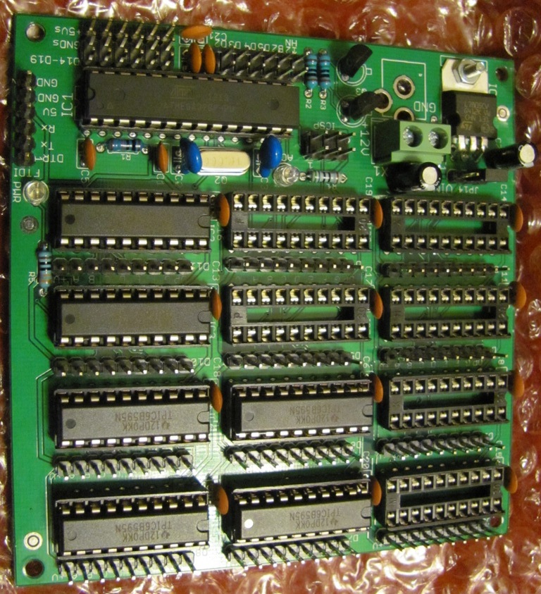
This board has 12 high current shift registers (TPIC6B595 is much better than 74HC595 for current sinking),
I have daisy chained 2 boards (2nd board just had the shift registers) to drive an 5x20 matrix of 12V LEDs, the caps make it work smoothly. http://www.crossroadsfencing.com/BobuinoRev17/
Need to make blanc match the hardware too, I think this is the change needed:
// 21 = PD0 #define blank_pin 21// same, can use any pin you want for this, just make sure you pull up via a 1k to 5V
PORTD |= 1<<blank_pin;//The first thing we do is turn all of the LEDs OFF, by writing a 1 to the blank pin
PORTD |= 1<<latch_pin;//Latch pin HIGH
PORTD &= ~(1<<latch_pin);//Latch pin LOW
PORTD &= ~(1<<blank_pin);//Blank pin LOW to turn on the LEDs with the new data
Might even go with 49 instead, PORTL bit 0, keep it all the same area of the same connector.
The latch from 2 to 10 ( SS )on the UNO or 53 on the MEGA didn't work
The rest i will try when i at home this evening, i'm at work now
Thanks so far
Need to make blanc match the hardware too, I think this is the change needed:
// 21 = PD0 #define blank_pin 21// same, can use any pin you want for this, just make sure you pull up via a 1k to 5V
PORTD |= 1<<blank_pin;//The first thing we do is turn all of the LEDs OFF, by writing a 1 to the blank pin
PORTD |= 1<<latch_pin;//Latch pin HIGH
PORTD &= ~(1<<latch_pin);//Latch pin LOW
PORTD &= ~(1<<blank_pin);//Blank pin LOW to turn on the LEDs with the new data
Might even go with 49 instead, PORTL bit 0, keep it all the same area of the same connector.
CrossRoad this also did't work
same results, few leds burning constant full power, no movement
Need to make blanc match the hardware too, I think this is the change needed:
// 21 = PD0 #define blank_pin 21// same, can use any pin you want for this, just make sure you pull up via a 1k to 5V
PORTD |= 1<<blank_pin;//The first thing we do is turn all of the LEDs OFF, by writing a 1 to the blank pin
PORTD |= 1<<latch_pin;//Latch pin HIGH
PORTD &= ~(1<<latch_pin);//Latch pin LOW
PORTD &= ~(1<<blank_pin);//Blank pin LOW to turn on the LEDs with the new data
Might even go with 49 instead, PORTL bit 0, keep it all the same area of the same connector.
Post the whole code again - I think the hard codiing for blanc and latch_pin need to be synced up, I had only discussed blanc, not realizing latch_pin might be in the same situation.
Okay, so pick 2 pins you can find & change these lines from:
PORTD |= 1<<blank_pin;//The first thing we do is turn all of the LEDs OFF, by writing a 1 to the blank pin
PORTD |= 1<<latch_pin;//Latch pin HIGH
PORTD &= ~(1<<latch_pin);//Latch pin LOW
PORTD &= ~(1<<blank_pin);//Blank pin LOW to turn on the LEDs with the new data
to these
digitalWrite (blank_pin, LOW); //The first thing we do is turn all of the LEDs OFF, by writing a 1 to the blank pin
digitalWrite (latch_pin, HIGH); //Latch pin HIGH
digitalWrite (latch_pin, LOW); //Latch pin LOW
digitalWrite (blank_pin, HIGH); //Blank pin LOW to turn on the LEDs with the new data
Will be a touch slower, can improve that once you get it working again.
Sorry but i got it working a few hours ago
A guy on a dutch Arduino forum helped me also and came with the solution
It had to something do with PORTD he changed it to PORTE
")