I thought I'd reach out to the sellers of this module to see if they could provide some useful information.....
Great customer support from chinese eBay and AliExpress stores 
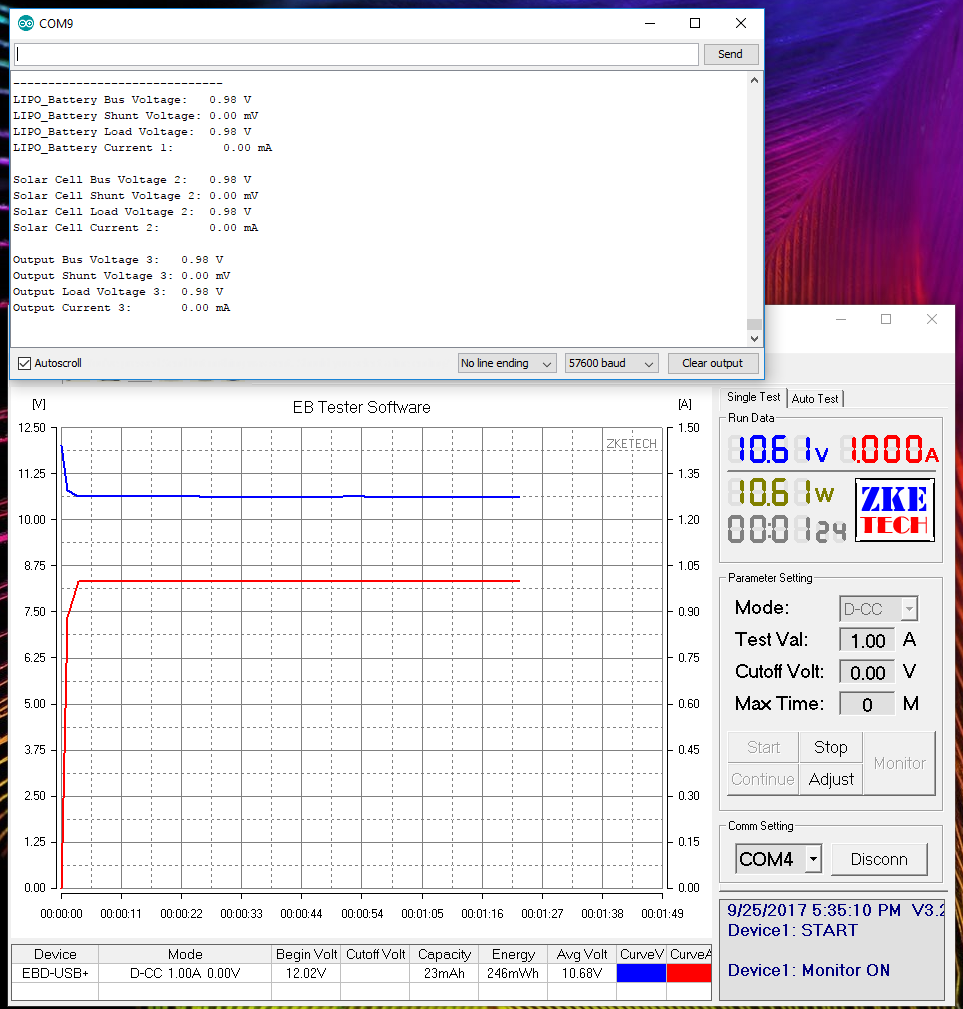
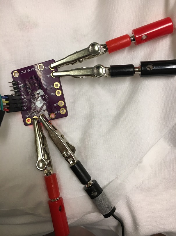
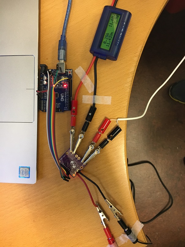
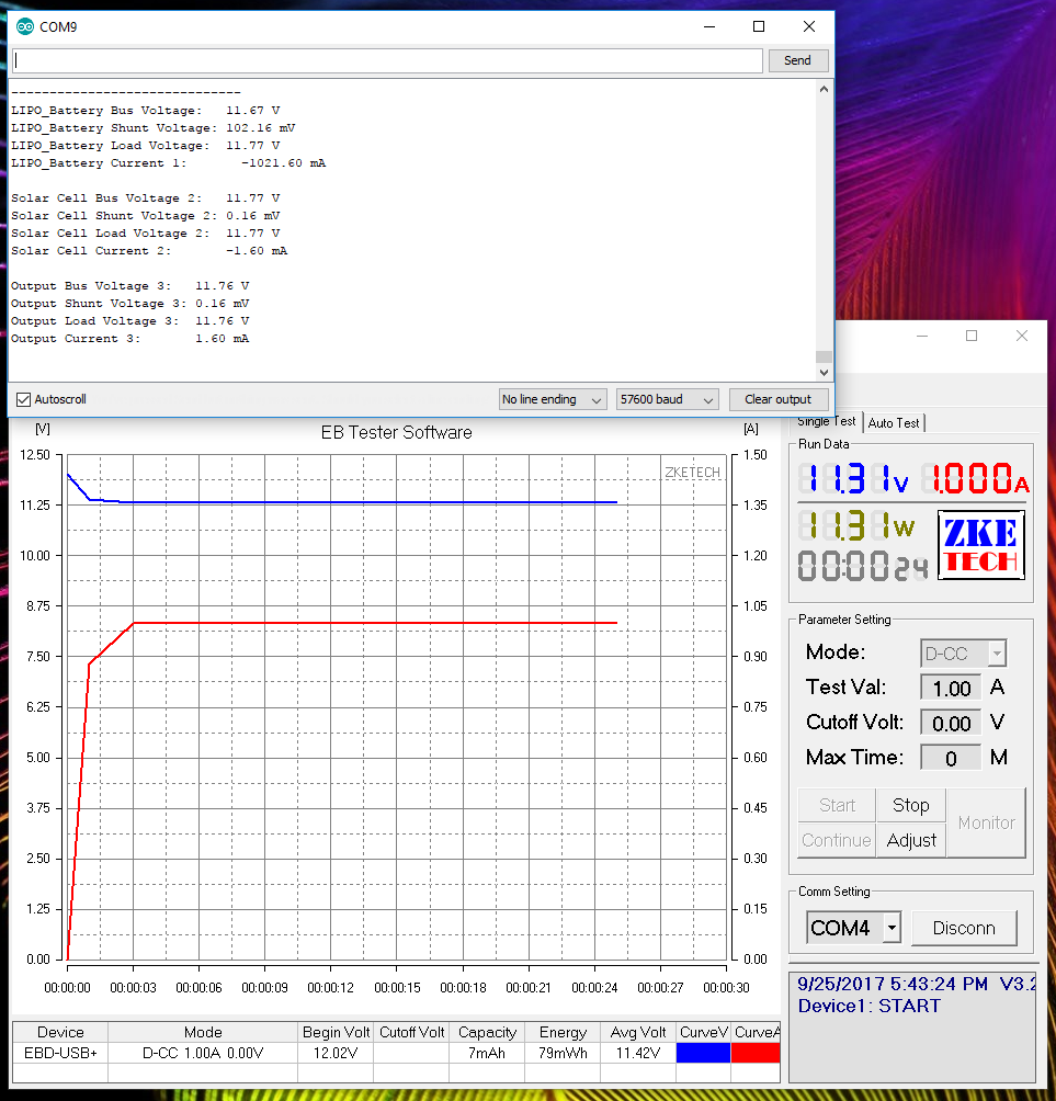
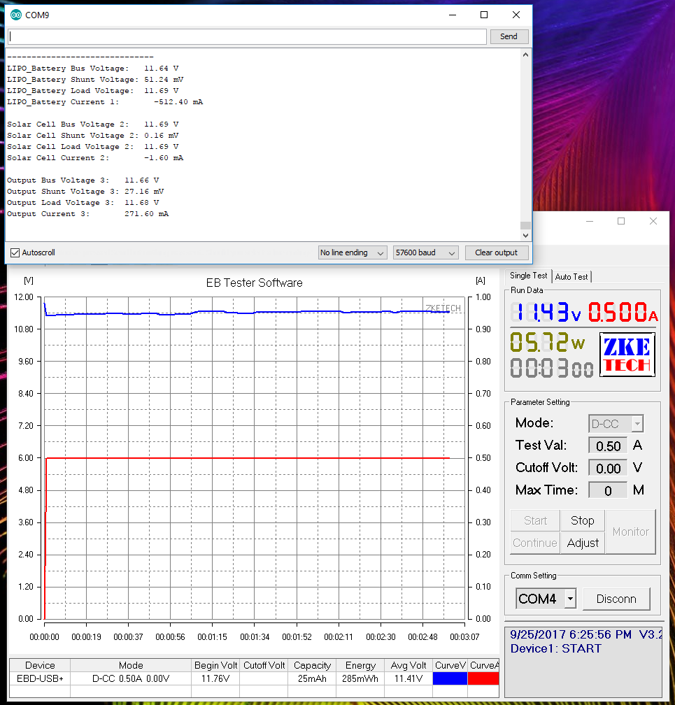
I will set up a test this afternoon with testloads on the three channels and try it high side and low side to see how that works out.
New message from: deepenmind (13,797YellowShooting Star)
Thanks for your email.
Sorry, I am just a customer service.
I tried my best to found some information for you, but sorry have no result.
We actually have no enough technical information can offer.
I hope to get your understanding.
Do you mind searching information online to find more technical support?
Thank you.
Best regards.
New message from: alice1101983 Top Rated Seller(372,646RedShooting Star)
Dear friend ,
Thanks for your email.
Sorry , I am just a customer service.
I tried my best to found some info for you ,but sorry have no result.
We actually have no enough technical information can offer .
I hope to get your understanding.
Do you mind searching information online to find more technical support ?
Thank you .
Best regards .
xiao meng
17/09/24 23:47
Dear friend ,
Thank you for your email .
But sorry that I am not sure about it.
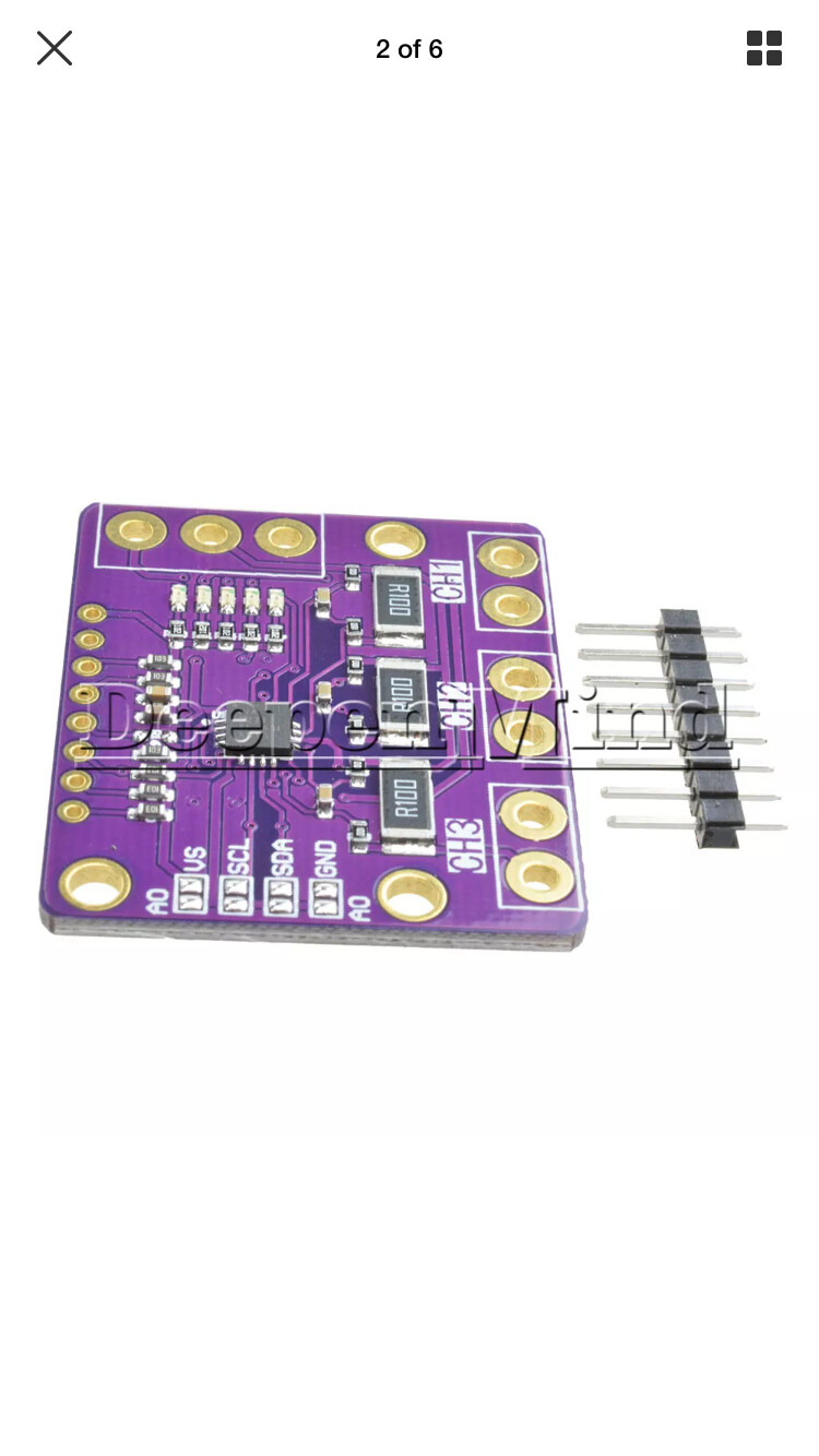
I can make sure that our items are as shown in the figure and item’s description .
If you need any help ,
Pls contact me anytime .
Best regards .
Arduino China
17/09/25 02:23
Dear friend,
Thanks for your email.
For more detail you can find it on our item description.
Do you mind finding it or searching information online to find more technical support?
Your understanding will be highly appreciate.
Best regards.
zhang tao
17/09/25 03:32
Dear friend ,
Thank you for your email .
But sorry that I am not sure about it.
I can make sure that our items are as shown in the figure and item’s description .
If you need any help ,
Pls contact me anytime .
Best regards .