I'm currently trying to automate a model railroad turntable. In order to align the tracks, I've got an LDR installed in front of each track, at the base of the turntable pit. Two 1mm holes drilled above each LDR allow light to get through from the overhead lighting above the layout. The idea is that when the turntable bridge reaches the 1mm holes, the LDR will go low and the Arduino will know where the tuntable is. From there, it's only a certain number of steps on the stepper to align the tracks. That's the theory, anyway.
What's actually happening is that the first couple of tests will line up correctly, then the turntable will start overshooting or undershooting. There are also times when the sensor seems to be triggered by the overhang off the side of the turntable bridge itself, rather than the base of the bridge. Yet all I've done between these test runs is push the 'reset' button.
I want to have the optical sensors trigger the Arduino when the turntable is above the holes, in the same location each time. Based on my poking around, adjustments to the threshold values used to determine if the LDR has gone low or not seem to improve accuracy, but the overshooting & undershooting still happens.
The LDRs themselves are set up as per the analog configuration here: Tweaking4All.com - Arduino - Playing with a light sensitive resistor (LDR). I tried with the 10K variable resistors, and couldn't get those to work. I've also attached my code. There are no delay functions in the code that's used to read the sensors or move the turntable itself.
Can someone please tell me what's going on, and how I can get these LDRs to trigger the Arduino (Mega) at the same location each time?
Tbdanny:
Two 1mm holes drilled above each LDR allow light to get through from the overhead lighting above the layout. The idea is that when the turntable bridge reaches the 1mm holes, the LDR will go low and the Arduino will know where the tuntable is. From there, it's only a certain number of steps on the stepper to align the tracks. That's the theory, anyway.
Not the best choice, IMO. Read about LDRs, specifically latency (response time). Depending on ambient light for this application is also less than optimal. You'd be better served with a LED/phototransistor pairing or, maybe a hall switch/magnet setup. Depends how you want to go but imagine a hall switch at each possible track position. On the turntable is the magnet to activate the switches. This eliminates the ambient light issue and gives a much faster and more consistent position sensing.
There are several regular posters here who have layouts, they can probably offer some better advice.
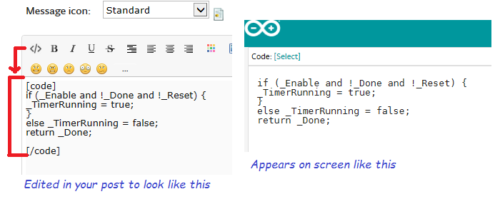
It would speed things along, too if you could post a MCVE of your code set within code tags like so.
Write a short program just to read the LDRs and report the values returned for various settings of the turntable.
Use that information to adjust the resistor value in the voltage divider (starting with 100K; possibly much higher), and to decide on a stable trip point.
With voltage divider resistance values > 10K, you need to add a 10 nF capacitor from the analog input to Arduino ground, in order to have stable readings.
You may also have to drill larger holes to get adequate light on the sensor.
The main reason I went for small holes was so they weren't so noticeable from the top. I'm trying to find an indexing system that's invisible or unnoticeable.
I've got a model railroad turntable, which I'm currently trying to automate with a NEMA17 stepper motor and an Arduino Mega. However, I'm having problems with getting an accurate read on the positioning of the turntable bridge. So far, I've tried three approaches:
Using a single hall effect sensor, and having the turntable move a set number of steps. This failed as the number of steps required to get to each track kept changing, resulting in the turntable needing to be constantly re-calibrated. Following this, I realised I needed a sensor for each track.
Using an LDR at each track. These were mounted under 2 1mm holes, drilled at the center of each track. I didn't want to use a larger hole, as I wanted them to be unnoticeable. However, these didn't trigger in a consistent manner.
Cutting a small section of the turntable pit rail (isolating it), and connecting that to an Arduino input. A wiper on the underside of the turntable bridge would then make contact with this section of the rail and pull it low, which would be detected by the Arduino. This didn't work, as the wipers didn't make sufficient contact, and as such this approach didn't work either. (This also caused the turntable bridge to 'float' off its base.)
At this point, I'm at a loss for what I can do to check the turntable position. I'm trying to find something that won't have too much of a visual impact (so no sensors above 'ground'), but will be accurate and trigger in a consistent manner every time. Can anyone offer any suggestions?
Unfortunately, I did not. The turntable and tracks were installed a few years ago. At the time, it was driven by a DC motor and gearbox, controlled by a rocker switch. It's now got full scenery done, and the tracks are ballasted. So moving them isn't really an option.
I've been using microstepping to try and align the tracks, with an A4988 set to 16 microsteps to give the resolution I need. Hence, I'll need a reference point for each track.
What is the scale, H0, N or what? I can think that the momentum needed at start as well as the torque needed when running is too low. Do You have any NEMA 23 laying around?
A standard steps per revolution is 200 steps, 1.8 degrees. I wonder if that is good enough. Using double, triple and quadruple stepping makes the stepper produce less of torque.
If Your stepper driver uses current controll You raise the stepper pwr voltage to get more torqe.
It's On30, so HO gauge tracks, and models that are built on HO scale mechanisms. I have tried checking without microstepping, and it doesn't line up closely enough with the tracks. I also tested the NEMA17 with a load equivalent to my heaviest loco in microstepping mode, and it moved it without any issues. I don't have a NEMA23 stepper motor at the moment.
One thing I have just found, when I googled NEMA23, was that there are 'dual shaft' motors available. Something similar to this: https://www.omc-stepperonline.com/Dual-Shaft-Nema-17-Bipolar-59Ncm-8378ozin-2A-28v-42x42x48mm-4-Wires.html. It's got the same rating as the single-shaft NEMA17 I've got under the turntable at the moment. I'm thinking that I could use the second shaft to install some sort of positioning system under the layout, which would be invisible from the top.
Could you potentially use a solenoid to pull back a wedge shaped pin while the track is moving and when you are really close, release the pin to slide into a matching wedge shaped hole on the turn table? That would force the table to move into alignment.
Using an LDR at each track. These were mounted under 2 1mm holes, drilled at the center of each track. I didn't want to use a larger hole, as I wanted them to be unnoticeable. However, these didn't trigger in a consistent manner.
In my experience getting LDRs to work reliably requires careful choice of the companion resistor that makes up the voltage divider. What value have you used? I have found that in my low-light situation I have to use 220k resistors.
However LDRs are slow to react so may not be suitable, even with an appropriate resistor.
Cutting a small section of the turntable pit rail (isolating it), and connecting that to an Arduino input. A wiper on the underside of the turntable bridge would then make contact with this section of the rail and pull it low, which would be detected by the Arduino. This didn't work, as the wipers didn't make sufficient contact, and as such this approach didn't work either. (This also caused the turntable bridge to 'float' off its base.)
In your other Thread I explained how I solve the problem by using a servo to extend a pin that blocks the movement of the table at the correct position, though I can see how that might require a few servos if the connecting tracks are spread around the circle. I also suggested that active optical sensors would suitable, including mentioning the QRE1113. They work quickly and very precisely.
I've got 12 tracks for the turntable, 11 locomotives plus the exit track. My understanding is that the copper wire extended from the tracks was surface-mounted, and as such, visible. Also, how much of a hole would the QRE1113 require to be able to 'see' something like a bright white spot on the underside of the turntable bridge?
Having said that, I am going to go for the idea of using a double-shaft stepper motor, and as such, putting the positioning mechanism under the layout. As such, that would allow me to implement the copper-wire and servo method 'out of sight'. I imagine something small, like a 9g servo motor would do?
Take a look at existing solutions.
I only know the really old Maerklin design using a metal pin sweaping the circumstance. When a track comes in front of the bridge the spring loaded pin went into the hole and motor current was also cut off.