I am not too sure what those graphs are off. Also how have you got these signals wired into your arduino.
An error of 20mS seems very high. I assume you get this error from seeing what your reading is and measuring it on an oscilloscope.
A lot will depend on the way you are reading the signals on your arduino and what frequencies they actually are. There are several methods. For the most consistent results I would:-
Make the input signal clean by using a compatator before feeding it into pin 2.
Make pin 2 trigger an interrupt. In the interrupt service routine set a flag and store the current value of the millis() timer. That should get you to 2mS accuracy.
If that is not enough there are other tricks but they are more complex.
Thank you for your answer... So 20 ms is too big...
I'm also going to check if it comes from the R/C receiver. I'm using a cheap E-Sky for the tests, with tired batteries, maybe this could improve the noise.
The joined picture shows the Sparkfun wires I use to input the PWM signals, and the following code is one of the two I'm using.
It reads 4 different ports and sends the measurements to an embedded PC (Pico-ITX) through a serial port.
I code each measurement with an ASCII character, so I have a resolution of 4 ma, which would be sufficient for me... But 20 ms is a little bit bigger !!!
Best Regards,
Stéphane
 // Reading 4 PWM signals from R/C receiver with interrupts
 // For an Arduino Mega 2560
 // And sending to serial port

 unsigned int servo2; // servo value
 volatile long count2; // temporary variable for servo0

 unsigned int servo3; // servo value
 volatile long count3; // temporary variable for servo1

 unsigned int servo18; // servo value
 volatile long count18; // temporary variable for servo2

 unsigned int servo19; // servo value
 volatile long count19; // temporary variable for servo3

 // PIN 2
 #define int2 (PINE & 0x10)

 // PIN 3
 #define int3 (PINE & 0x20)

 // PIN 18
 #define int18 (PIND & 0b00001000)

 // PIN 19
 #define int19 (PIND & 0b00000100)

 void handleInterrupt_P2()
 {
  if(int2)
    count2=micros(); // we got a positive edge
  else
   servo2=micros()-count2; // Negative edge: get pulsewidth
 }

 void handleInterrupt_P3()
 {
  if(int3)
    count3=micros(); // we got a positive edge
  else
   servo3=micros()-count3; // Negative edge: get pulsewidth
 }

 void handleInterrupt_P18()
 {
  if(int18)
    count18=micros(); // we got a positive edge
  else
   servo18=micros()-count18; // Negative edge: get pulsewidth
 }

  void handleInterrupt_P19()
 {
  if(int19)
    count19=micros(); // we got a positive edge
  else
   servo19=micros()-count19; // Negative edge: get pulsewidth
 }

 void setup()
 {
  Serial3.begin(9600);

  // PIN 2
  attachInterrupt(0,handleInterrupt_P2,CHANGE); // Catch up and down

  // PIN 3
  attachInterrupt(1,handleInterrupt_P3,CHANGE); // Catch up and down

  // PIN 18
  attachInterrupt(5,handleInterrupt_P18,CHANGE); // Catch up and down

  // PIN 19
  attachInterrupt(4,handleInterrupt_P19,CHANGE); // Catch up and down
 }

 void loop()
 {
  unsigned char val2;
  unsigned char val3;
  unsigned char val18;
  unsigned char val19;
  unsigned int chk;

  delay(5);

  val2 = (int)(0.252*servo2-251);
  if (val2 < 1)
    val2 = 1;
  if (val2 > 253)
    val2 = 253;

  val3 = (int)(0.252*servo3-251);
  if (val3 < 1)
    val3 = 1;
  if (val3 > 253)
    val3 = 253;

  val18 = (int)(0.252*servo18-251);
  if (val18 < 1)
    val18 = 1;
  if (val18 > 253)
    val18 = 253;

  val19 = (int)(0.252*servo19-251);
  if (val19 < 1)
    val19 = 1;
  if (val19 > 253)
    val19 = 253;

  // Cheksum computation
  chk = val2 + val3 + val18 + val19;

  while (chk>253)
    chk = chk - 253;

  Serial3.write(254);
  Serial3.write(254);

  Serial3.write(val2);
  Serial3.write(val3);
  Serial3.write(val18);
  Serial3.write(val19);
  Serial3.write(chk);

  Serial3.write(255);
  Serial3.write(255);
  }
Thank you for your answer... So 20 ms is too big...
I'm also going to check if it comes from the R/C receiver.
I don't think I'm following this.
Are those the PPM signals within an R/C receiver, before the demultiplexer?
Why the positive and negative-going excursions?
20ms is the entire frame time of a standard R/C PPM/PWM stream.
If you have an error of 20mS this means that you know the signal range.
I have asked you for the frequency but you have not told me.
The 20mS error, what is that in terms of a percentage error?
I suspect you might be leading us astray with your incorrect use of the word error. A 20mS error would happen if you read a signal of xmS and you got a reading of x +/- 20 mS.
Hi,
Try my code from this blog post, many others are using it successfully -
Your code has at least one major problem which is that there is no protection on shared variable access, in which case you data will generally contain nonsense as you are experiencing. Read the post above to see why, then try the sample code provided and let me know if you see an improved result.
OMG, I'm so confused (shame on me)... In fact, I didn't provide you the correct unit.
The error I get is not 20 ms, but 20 µs !!!!!!! I'm so sorry for this misunderstanding... !!!!!!
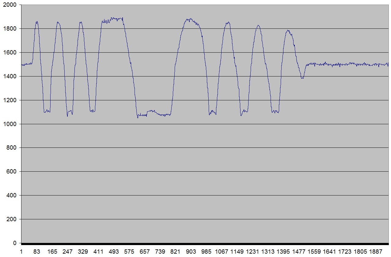
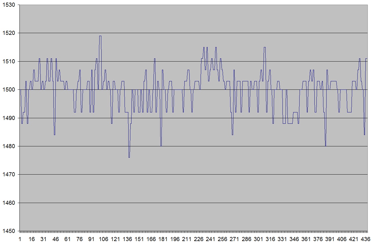
In fact, Grumpy_Mike, the embedded PC gets the measurements with a rate of 80 Hz (I think it comes from the serial port which is, for the moment, configured at 9600 bauds...). And I joined the second picture (in my first post, which is a zoom in of the first one) to illustrate the error I was talking about.
If I don't touch the Radio sticks, the mean is 1503 µs, but I got a lot of 1511 µs measurements and 1492 µs measurements...
Hi,
Yes I do get a 4 or 8us error, its is unavoidable and due to interrupts queuing up. For example if a timer fires, then an input pin goes high and then another input pin goes low, one of the ISRs will have to wait for the other complete one after the other before it can be serviced, this takes around 8us.
It works out at about a 1% error across the 1000us to 2000us range of an input signal.
Hi,
Thinking about it, your data is a lot less stable than mine, I tend to get a steady 1504 which will occasional read 1500 or 1508. This is since I changed radios to a Spectrum 2.4 Ghz radio, with my previous 27Mhs AM Radio, my readings were like yours and deteriorated very badly over distance - my application runs in my RC Race cars at 200 meters distance moving at 40Km/h.
See here for some more information -
Data from my 27Mhz and a strategy to clean it up
Data comparison with new radio
In your case, depending on your application and if you do not want to invest in a new radio, a simple smoothing algorithm might be your best option.
Thank you very much for your posts, and especially for the links to your blog which is very instructive and contains a lot of information !!!!
In fact, I think that my bigger errors could come from the fact that:
I read 4 inputs in the same time (according to your interrupts queuing explanation, this could decrease the accuracy)
I encode the signal with a ASCII-like octet (to be sent by the UART) and I decode the signal, so I have a resolution of 4 µs which add additional error
I performed the ‘table’ tests with a E-sky radio which is maybe not the best one..., but I have a MX12s for my Oktokopter
The project I have is to read the PWM commands input (of a DJI NAZA board) and the gyroscopes rates of an Oktokopter, to be able to determine its non linear model, and after hours of Google, I have concluded that the Arduino board was the best solution to transform PWM signals into UART… !
You also right, I really have to smooth the commands, I think I’ll test your algorithm !! If I find another one, I’ll provide it to you…
I didn't progress the development of that algorithm as my new radio improved the quality of the input data to the point that I no longer needed to smooth it.
The other reason I didn't progress it is that the car motor and steering respond much more slowly that the Arduino is able to measure the signals. In effect the car has built in signal smoothing just because the mechanical components have momentum and are unable to react at digital speeds, so the signal noise cancels itself before the car is able to respond.
There are quite a lot of smoothing algorithms around that average across multiple samples, these provide better results than my algorithm, but require more memory to hold multiple samples for each channel and will respond less quickly to large moves in the control input. If you keep the number of samples low memory and response speed should not be a problem, I would suggest you try this rather than my algorithm.
You are right, our platforms have "mechanical momentum" which smooth the signals...!!
However, in my case, these "mechanical momentum" are a part of the non linear model, and to determine it, I really need the commands sent to the engines...
I think that if I realize that my mx12s radio is not efficient enough to have a clean signal, I'll use the following strategy:
Using a high rate acquisition (in setting up the UART baudrate at 115200)
Performing an offline smoothing algorithm (no need to do it online, since I just do data acquisition)
Then crossing finger in testing several approaches as you mentioned: Sliding mean, ...
I'll keep you informed of the results (^_^)