I'm here because i'm facing a problem where i'm running a board on which i have 2 big servos (17kg/cm).
Firstly, let me tell you that i'm a noob in electronics.
Let's say, i'm beginning in switching regulators.
Until now, everything was running fine but suddenly, it seems that my +5V is unstable.
My voltage regulation is based on a "LM2576T-5.0 P+".
Symptoms :
When i plug the +12V on my circuit, it refuses to power on everything until i disconnect the 2 servos.
If i plug one of the servos, then everything powers off (protection mode of the LM2576 i think)
When the system is not powering on, if i mesure the normally +5V, it is +1,95V.
The system won't handle load correctly (if it goes further than 1A, it resets like power is cut then back on then cut then back on etc ...)
I have 2 feelings :
The inductor (100µH) seems to be a 1/2w (you know the axial ones ; green color ...) ; i think i made a big error when buying it because it is clearly not supporting 3A !
Could it be the LM2576T-5.0 which was running without heatsink and i don't know if it has suffered from high temperature of today as my circuit is located outside in a closed box of approx. 30cm X 20cm X 10cm. (I did a calculation of the heat sink and it seems it requires, for 3A, a 20°C/W heatsink ; but as it is not running 3A frequently, i thought it was useless to add a heatsink for now ... finally, maybe not)
It definitely sounds like your inductor is under-rated. I'm not sure what the "1/2W" rating is -- inductors are usually rated by current (among other things). If you're planning on delivering 3A then you need a power inductor that has a saturation current rating of at least that, preferably more. I doubt an axial "green inductor" is even close.
I think you want something more like this:
--
The Gadget Shield: accelerometer, RGB LED, IR transmit/receive, speaker, microphone, light sensor, potentiometer, pushbuttons
Rugged beat me to it but in addition I would say that a switching regulator is a very tricky thing to build. You need a good PCB layout and even experienced engineers often take two or three attempts at getting it right.
How is yours physically constructed?
LM2576T-5.0 (a new one because i'm not actually sure if mine is healthy)
a GOOD inductor (toroid type this time with at least more than 3A of DC current)
a heat sink of max. 20 C/W (and some thermal gel to conduct heat)
Hope this time everything will run OK for more than 1 week.
I think my PCB is well done because it worked fine from start.
Even when i was on the breadboard, i never had problems with heavy loads like when my 2 big servos were moving at the same time.
What i didn't know was the fact that even switching regulators deliver less heat, they do require a heat sink. Moreover, they do require an inductor that is at least of the max DC current the regulator is able to deliver... Hahaha big mistake for me here ! Shame on me ...
I've used LM2576 twice and never had problems with it. Very easy to get it work.
At the first time I made some tests, and with 2A it does not heat much.
Have you tested with some other load than your servos?
I think my PCB is well done because it worked fine from start.
That does not follow, if it stopped working that is because it was not alright.
You need to look closely at the waveforms on an oscilloscope to detect instability under a variety of loads.
The PCB layout you have is very naive, it is a poor layout. Has the data sheet got any recommended layouts?
I would expect much more copper and more attention to ground return paths.
I used the maximum available of Fritzing
No excuse. Physics doesn't care, it needs to be right.
ok, so i think i found the answer to my question "why was it working until now ?!?!" ...
i took a closer look at the very poor inductance i put on my board (axial green 100uH) and saw that it has a crack on its side.
i think this is the point why it suddenly stoped working.
definitely, this little inductance was clearly a problem from start and i didn't saw it at first (remember, i'm an electroni-noob).
i managed to find the good inductance in an internet store so now i'm going to wait for it to come and wil report back if there is still any problem.
for testing, i'l try to use the actual LM2576T-5.0 and se if it's working normaly with this new inductance, which is the recomended one based on the datashet (PulseEng PE-92108K).
of course, i bought 2 others LM2576T-5.0 to be sure mine is not in quite-dead condition.
i have done some changes on my PCB because the good inductance is very large compared to the thin cracked one owho was actualy on my board.
by the way, could you please indicate me a god PCB layout for it to run smothly ? ( do i have to fill my PCB with copper for acting like thermal heat sink ? )
Well well wellllll ... Fritzing doesn't support multiple tracks between the same components ... Pfffff ... I should have chosen another PCB Layout design software ... Now i'm on Fritzing, i'm on fritzing !
Ok, so as i can't duplicate tracks, for the moment, i made some changes, please tell me what do you think of this new PCB :
While more copper is good, the layout is still poor.
That schematic is telling you to implement a star ground with pin 3, the anode of D1 and the negative leads of Cin and Cout.
You have them in a chained arrangement. What you need to do is arrange these components to join together at only one point to prevent any inductance in the ground return path.
That is the first step towards getting it right.
While not exactly the same chip, it basically is - I am using the LM2596
I have created a test board, which I ended up routing wrong, actually had a component in the wrong spot, however have reworked the circuit as a trial and got it working well, so have adjusted the design and will get the next revision printed.
Here is the Top and Bottom prints of my circuit. I have had very little input from other people, so any critique is welcome before I get it printed.
NOTE: The company I get my boards printed cannot print Plated Through Holes (ie Via's), so I have to manually do them with a resistor leg soldered each side. It is a downside, however at around $10 - $15 for a single ($5 - $10 US) 80mm x 80mm board, its perfect for prototyping.
Anyway, this may be of some use to you.
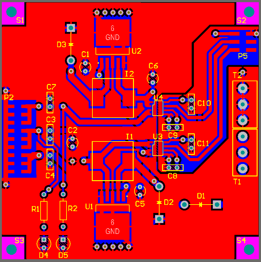
Red is top layer, Blue is bottom layer. Done in Altium Designer.
So i made some changes reflecting what you have told to me.
By the way, i wanted to thank you for your help because i couldn't determine that the ground should be done as a star.
I think you will be proud of me now ... errr ... i hope !
Have a look :
EDIT (2 things) :
1st : Fritzing is alcoolic so do not bother why the holes are quite full of copper
2nd : i had to let space between the diode and the LM2576 because i have to put a heat sink so i evaluated the good space as is on this PCB.
ONE MORE EDIT :
I finally found how to increase track width (by asking on Fritzing forum ...) so now the tracks around the LM2576 and the +5V / +12V / GND of my board are 80 mils !!! yeehaaaa !
Yes I am proud of your attitude to learning, keep it up.
Unfortunately I don't think you have got the idea about star grounding. The arrangement is that all the grounds go to the one point. So let's say the star point is the ground on D1. The LM2596 should go straight to D1 no where else. Likewise the track from C2 should go directly to D1, no where else. The track from C2 should go to D1, no where else. So if you follow the paths that the ground current can take it goes from each component to that point, no where else. Any current path to the star point never has the current from two or more components flowing through it.
The star point can be anywhere, not just D1, maybe best on the LM2596 or some other point not on a component, but the principle is the same, short tracks, wide tracks, star ground.
OK on the gap between the LM2596 and the other components being due to the heatsink. Can you not turn the heatsink over and reduce that distance? It really will make it more stable. Physics is a cruel master.
And now teacher ? am i in the right direction ? is it good this time.
I understood the STAR POINT way of thinking.
I think this time is the good one
Please tell if i've done great job ] :
EDIT : I modified the location of the LM2576 in order to place the heat sink in the right place. Now it will fit perfectly.
So if you confirm that this will work, YEEEHAA !! let's make the PCB now !


