I have an optical encoder (16 segment) on a DC motor from an animatronic toy (the new 2012 furby) that I want to control with an Arduino (Uno). The encoder is easy enough to read directly from the carrier board via the blue and white wires when energized with 3-5 v (red/black wires). However, how can I discriminate between the forward and reverse directions?
Encoder board (encoder wheel not shown):
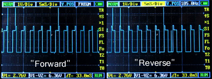
Oscilloscope traces:
I assume there is some way of telling apart the pulses with high leading edge VS pulses ending with high leading edge... but I have no clue how to do this with an Arduino. Any help would be greatly appreciated!
[edit: the chip shown is a Texas Instruments CD74HC14 chip that contains six inverting Schmitt triggers]
However, how can I discriminate between the forward and reverse directions?
Well it's built into the encoder in that there is a offset from the channel A and B beams such that the rotating grid will interrupt one channel before the other in one direction and of course when the direction is changed the channel seeing interrupt first will reverse. If it happens to not be correct, simply rewiring the channel wires will correct the situation.
This also relates to the direction the motor turns via the H-drive polarity allied to the windings, so there are basic set ups you have to test for and correct if needed, but it's usually just swapping two wires so all the phase relationships are correct.
However, how can I discriminate between the forward and reverse directions?
Well it's built into the encoder in that there is a offset from the channel A and B beams such that the rotating grid will interrupt one channel before the other in one direction and of course when the direction is changed the channel seeing interrupt first will reverse.
Lefty
Correct me if I am wrong, but there is only one channel for this encoder (one set of trans/rec)- you can see them on the back of the board (the side with no IC) and of course the encoder wheel travels between them.
Well if the sensor is a single channel then it's not an encoder at all but rather just a speed sensor. I can't tell from the rather small picture if it's a single channel speed sensor or a two channel quadrature encoder. Four wires should be enough for a full two channel quad encoder with, power, ground, channel A, and channel B wires?
retrolefty:
Well if the sensor is a single channel then it's not an encoder at all but rather just a speed sensor. I can't tell from the rather small picture if it's a single channel speed sensor or a two channel quadrature encoder. Four wires should be enough for a full two channel quad encoder with, power, ground, channel A, and channel B wires?
Lefty
Would a larger image help you to tell a single from a two channel quad encoder?
I'm still going with two channel outputs, mostly just based on the number of wires connecting the module. A speed sensor would only need/use three, ground, power, and signal.
retrolefty:
I'm still going with two channel outputs, mostly just based on the number of wires connecting the module. A speed sensor would only need/use three, ground, power, and signal.
Lefty
So oscilloscope trace for white/ground would give one channel pulses trace and blue/ground would give the other channel pulse trace? I did try that already and got no obvious pulse trace on the scope unless I used blue/white... or am I just doing something really stupidly wrong?
Encoder outputs are normally open collector and so you will need pull-up resistors on the signal wires. Repeat your tests with internal pull-up enabled on pins connected to blue and white.
BenF:
Encoder outputs are normally open collector and so you will need pull-up resistors on the signal wires. Repeat your tests with internal pull-up enabled on pins connected to blue and white.
Thanks!
I added pull up resistors between signal and Vcc for both and it now works (on the scope) as expected for both blue and white leads as two different channels. Thanks again for that simple tip!
Well... while both channels (blue and white wires) give nice square waves when the motor is running, one channel outputs 0 or 5 volts., the other channel outputs 0 or 0.5 volts.
Anyone have an idea why both channels would not be outputting the same voltage range??
Both channels have pull up resistors. Vcc is 5volts (red wire) and Gnd to black wire.
The same value pull-ups? Normally the detector is two phototransistors so the value
of the pull-ups has to to be about right for that phototransistor at the illumination level
it is getting - some experimentation might be needed. You will need to exclude stray light
too.
Yep- I get the same square wave (one channel is 0-0.5v, the other 0-5v) using either using external 100K Ohm pull up (not coneected to Aruino pins), or using internal pull ups on Arduino when connected to digital pins.
You will need to exclude stray light too.
Has the same behavior in complete darkness.
Seems like I am missing something really simple (again)...
Try 10k pull-ups - the high output voltage is set by the dark-current of the phototransistor - which is basically a leakage current,
and a smaller pull-up will lift that 0.5V. A perfect transistor would have no leakage and even a 10M resistor would pull up to 5V,
but transistors aren't perfect (in this example one is less perfect than the other by quite a factor).
Also 100k is a rather high impedance for logic circuitry, you'll get more cross-talk from other nearby signals with too high a value,
circa 10k is a pretty universal general pull-up value for CMOS logic.
MarkT:
Try 10k pull-ups - the high output voltage is set by the dark-current of the phototransistor - which is basically a leakage current, and a smaller pull-up will lift that 0.5V. A perfect transistor would have no leakage and even a 10M resistor would pull up to 5V, but transistors aren't perfect (in this example one is less perfect than the other by quite a factor).
Well, an exhaustive trace of the entire board reveals that the blue wire is actually ground, and the black wire is one of the encoder channels. A complete schema is attached for anyone else who might be hacking the 2012 Furby...